Building Magayon II
Yes, we are building a Wharram Tiki 26
Why a Wharram?
We first thought about building another Sharpie NIS23 like our first boat Magayon, but after studying many avaialble boat plans we settled for the Tiki26 design. Some of the reasons were:
- Lots of space for sailors and also for sleeping (up to 6 with deck tent). Magayon could only sleep 2 adults.
- For day sailing it can even accomodate a lot more people because of the much larger cockpit and deck area.
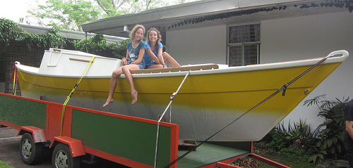
- The Tiki 26 can still be trailered.
- We never used the (larger) cabin of our 23ft Sharpie because here in the tropics it got too hot inside.
- Almost every component of the Tiki can be self made.
- Additional reasons can be found on the Wharram homepage.
Plans
So we finally ordered the plans hoping that we would sail within a two years timeframe.


Humble Beginnings
With a new contract for 5 years there is time for another boat building project. After a trip to Manila to source good quality marine plywooed, Martin found out that Makiling Hardware in Los Banos does have a stock of Santa Clara Plywood. It is manufactured in Cebu and also exported. Supposedly it is the best marine plywood that can be found in the Philippines. Since we don’t have a building location yet for the hulls we bought only a few sheets to start working on the bulkheads and the cross beams.
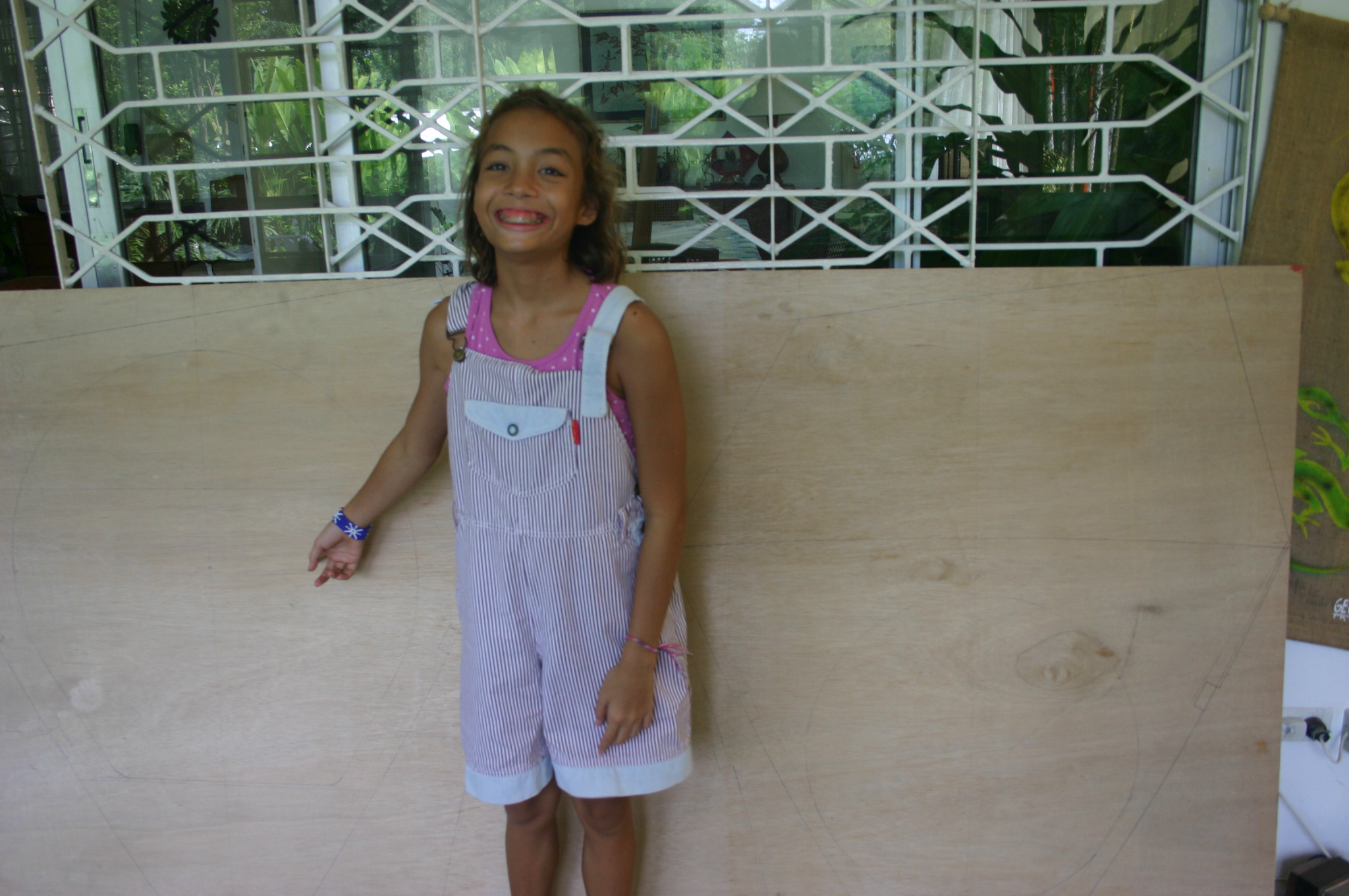
Miriam, after helping to transfer the drawings of the bulkheads onto the first board: “What? So small? We are supposed to sleep in there? We’ll get claustrophobic.”
We cut out four bulkheads, and then shelved this for some time because working on the cross beams seemed to promise earlier success experiences, something needed at this stage.
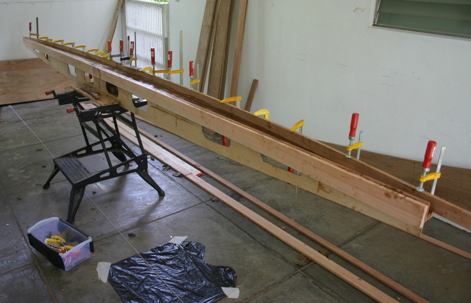
Making the Cross Beams
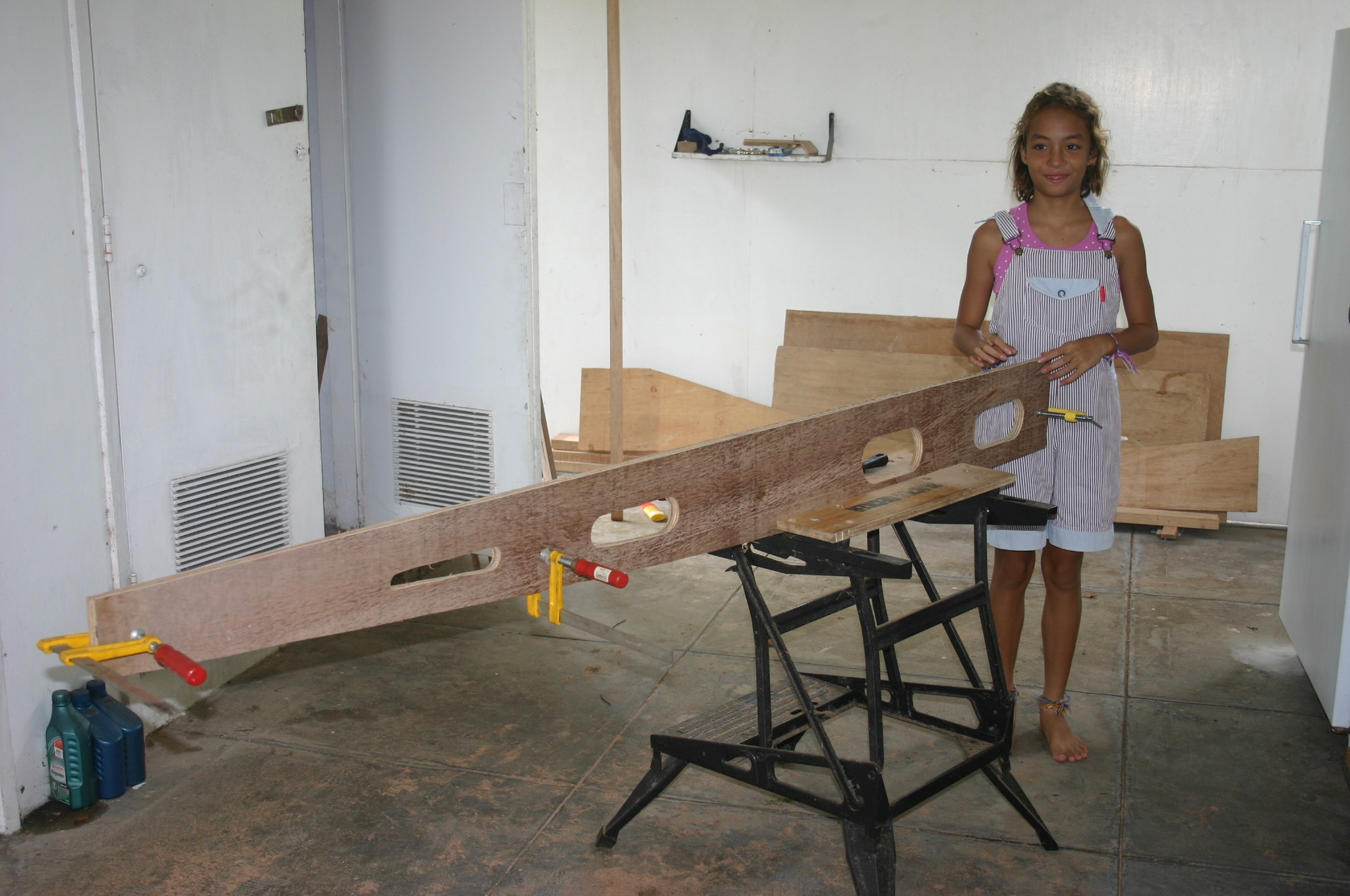
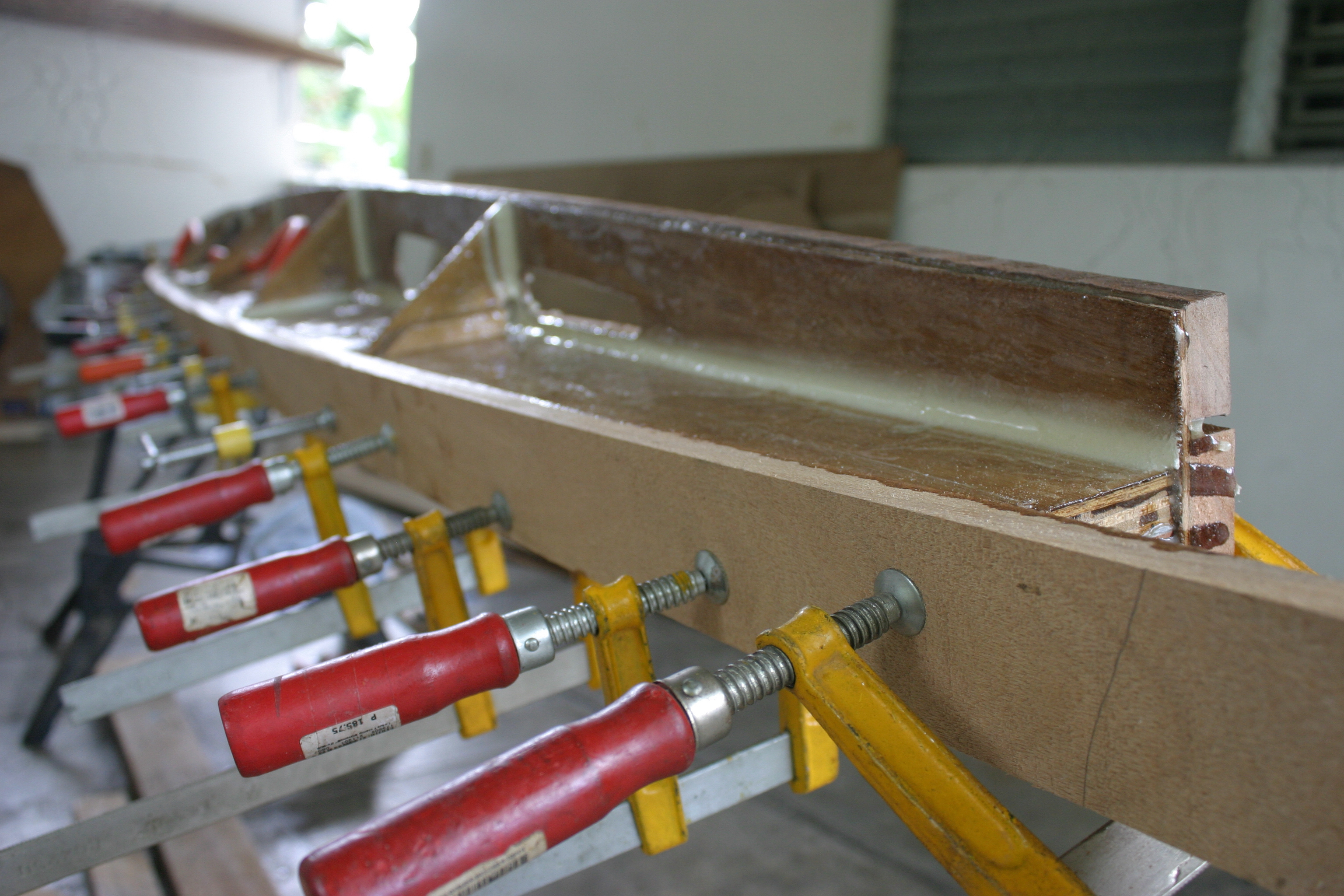
May 2009: The center cross beam under construction. This carries the mastfoot and therefore is the most complex of the three cross beams. It consists of of may different plywood parts and wooden beams, a good practicing piece for getting familiar with the different epoxy techniques, glueing, epoxy fillets, and glassing. Almost finished before our 2009 home leave in July 09.
The Center Crossbeam
March 2011: The boatbuilding project was on a hold for almost two years because restoring the BMW took all of Martin’s spare time. In January 2011 we took it up again by starting to build the aft cross beam.

In the meantime we looked for a building location for the hulls because the noise would have given our neighbours a hard time and we might have been thrown out of the housing complex where we live. Finding a site in Los Banos was not an easy task because every space is used somehow. Options assessed included a house ruine a friend wanted to by for rennovation, an open space at a Barangay Captain’s property at the lake down in town, renting a space at the institute and others. It was fruitless.
Some help was needed.
Getting Some Help With Building The Hulls
June 2011: At the speed the building was going at this point of time we would be sailing in 10 years, or maybe never. Martin therefore looked for alternatives like hiring some local people to build the hulls. But good local craftsmen are difficult to find and in high demand and the disaster of building Magayon, which fell apart after only six years due to lousy construction, did not make this option a very attractive one. After some research on the internet we found an accredited, professional Wharram builder in Bohol, called Junction Boatworks. We then decided to have the hulls and the mast built by Junction Boatworks. We wold continue building the third cross beam, cockpit and the gaff. We assumed that if everything works out fine we could be sailing on Easter 2012.
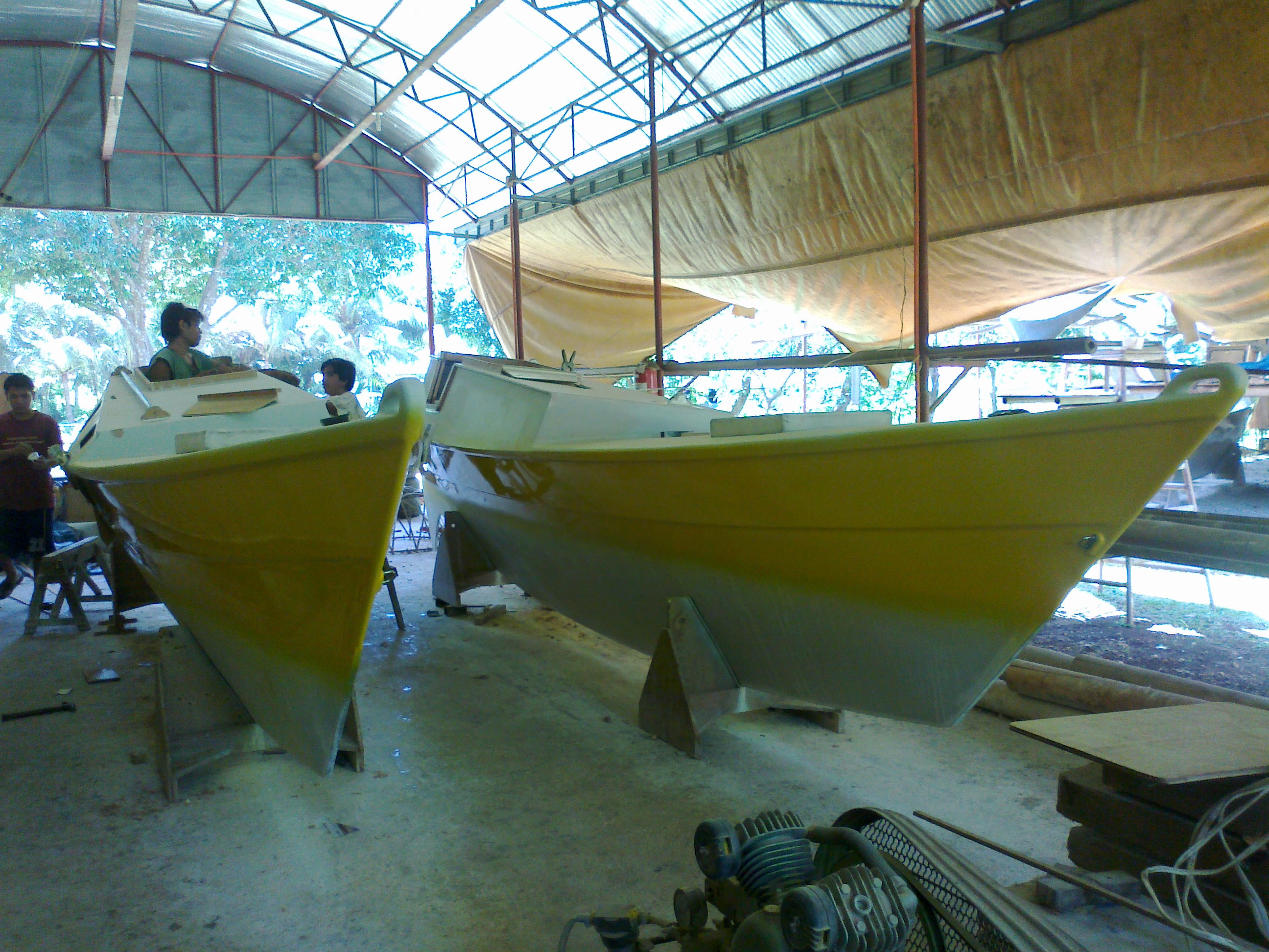
Martin flew to Bohol in June for a weekend to discuss the project with Andy Smith, the owner.

The picture shows another Wharram design being completed at the time of the visit at the Junction Boatworks boatyard.
Overall Junction Boatworks left a good impression so Martin asked for a draft contract for two hulls and the mast ‘according to the plans’ and after some discussions and revisions the contract was signed by both parties.
Progress
The first payment was made and Andy’s men went to work. They constructed the hulls in stich and glue technique without a building frame. A steel keel was proposed by Andy with additional charge. After some argument about having ordered the hulls “according to the plans” and the steel keel is included in the plans we setteled for half the amount.
Hullst turned around for mounting the steel keel.
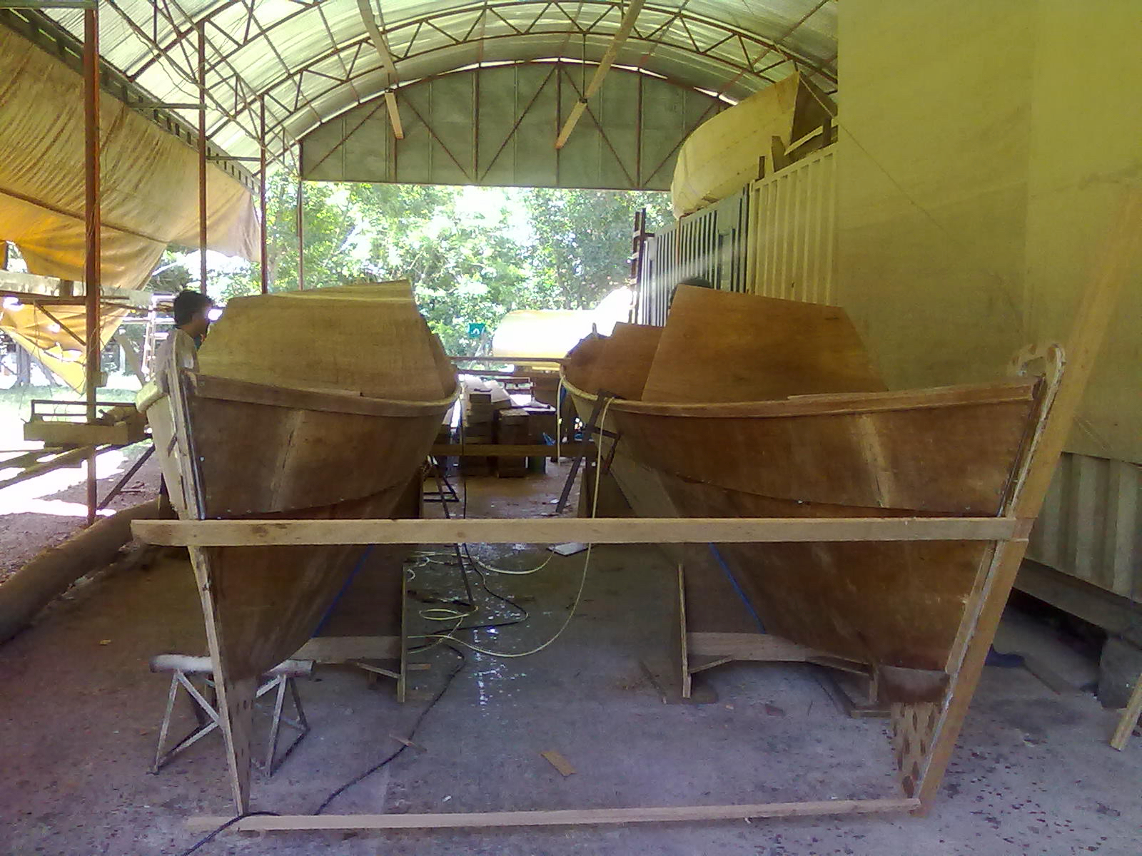
August 2011: Hulls up stage, Andi sent the pictures, what it meant besides the good news about progress was that the next payment was due.
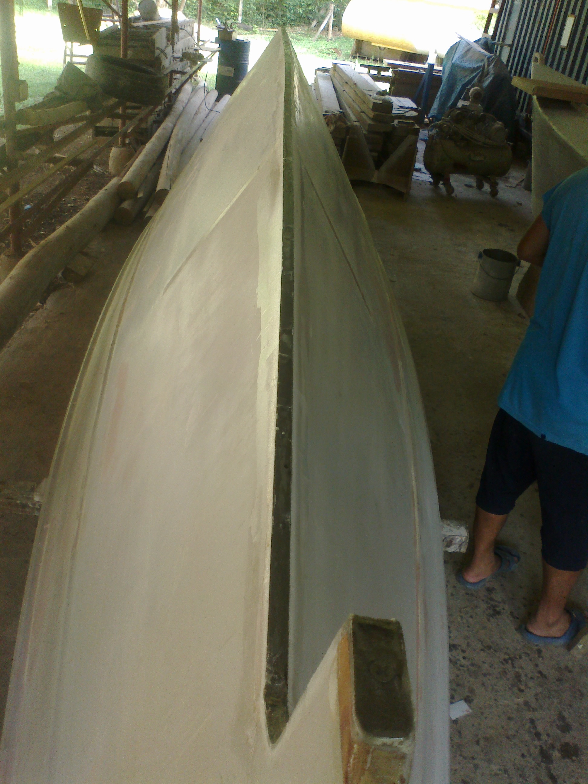
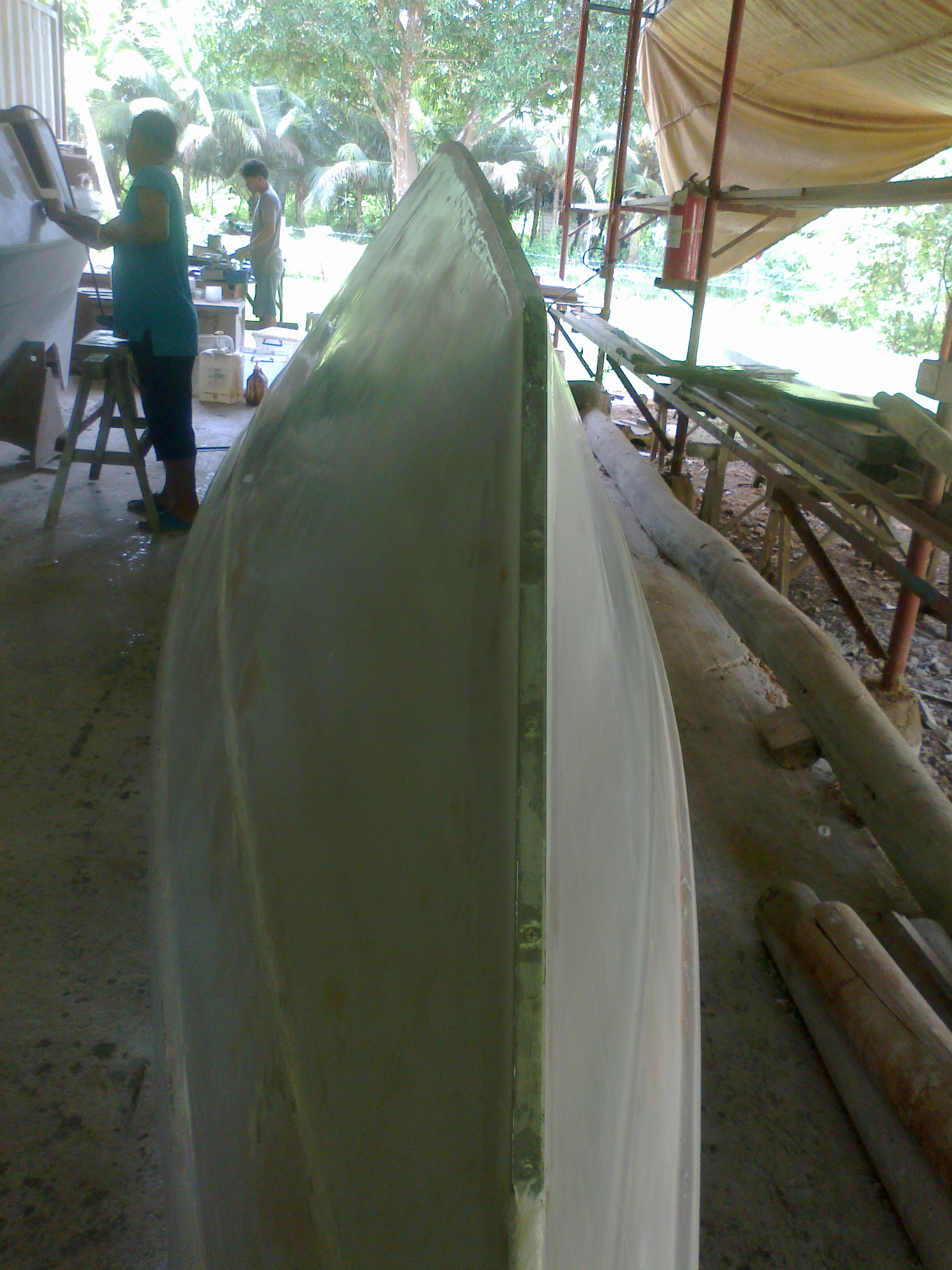
September 2011: Ready for painting stageWork progressed accordign to schedule, actually a bit too fast for our taste since we had not figured out the next steps, shipping to Luzon. Anyway, the next payment was made and the work progressed further.
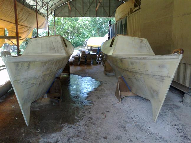
October 2011: Paint stageThe hulls are almost complete, Junctoin Boatworks sends the Photos. Time to think about shipping arrangements and make the last payment.
OK, so the next thing to do was getting the completed hulls to Lake Taal. Easy, one should think.
A Trailer and two Road Trips
The challenge was to get the hulls from Bohol to Lake Taal. The first quote we got from Andi Smith’s boatyard for shipping them via sea transport from Bohol to Manila and then by road to Talisay amounted to US$ 4,300. A rediculously high amount. Mavic then started getting inquriries from different shipping companies, all the initial quotes were in the US$ 1,000 range but when they came back with a more detailled offer it had usually increased to US$ 4,000 ++.
Fed up with this we then decided to have the trailer, which we would need anyway, and drive it down to Bohol to pick up the hulls.
See the video for loading the port hull at Andi Smith’s boatyard on top of the trailer.
Electrical Stuff
I have the intention to build the boat in a way that it could be sold easily in Europe. It therefore needs a proper electrical system. After all, the electrics of Sancara, which I designed and implemented, was a serious marketing point when Sancara was sold.
Design specifications:
- Lighting according to international regulations.
- Minimized power consumption, all light should be LED lights.
- It should have a power grid connection for land power supply in marinas. That of course would include a 110-220V battery charger
- Solar panels for battery charging
- Each hull has an automatic bilge pump with manual override
- Electronic log and depth sounder in one combination instrument
- Two cockpit speakers and one additional speaker inside each hull. IPod enabled car stereo that can be controlled via the IPad from the cockpit.
- Connectors for SatNav, radio and other navigation equipment
- Connector for peltier cool box
- One connector for other devices in each hull
- Drinking water pump in starboard hull
- To maximize the lifetime of the LED electronic LED voltage stabilizers are installed in each hull. For long (overnight) trips they can be turned off to safe energy.
- All electrical connections done according to the state of the art using suitable electrical connectors and cable end sleeves.
I started designing the electrics with the CAD software EAGLE, which has a free version just sufficient for projects like this. It started out quite simple, I then ordered electrical components and as a result the design increased in complexity.
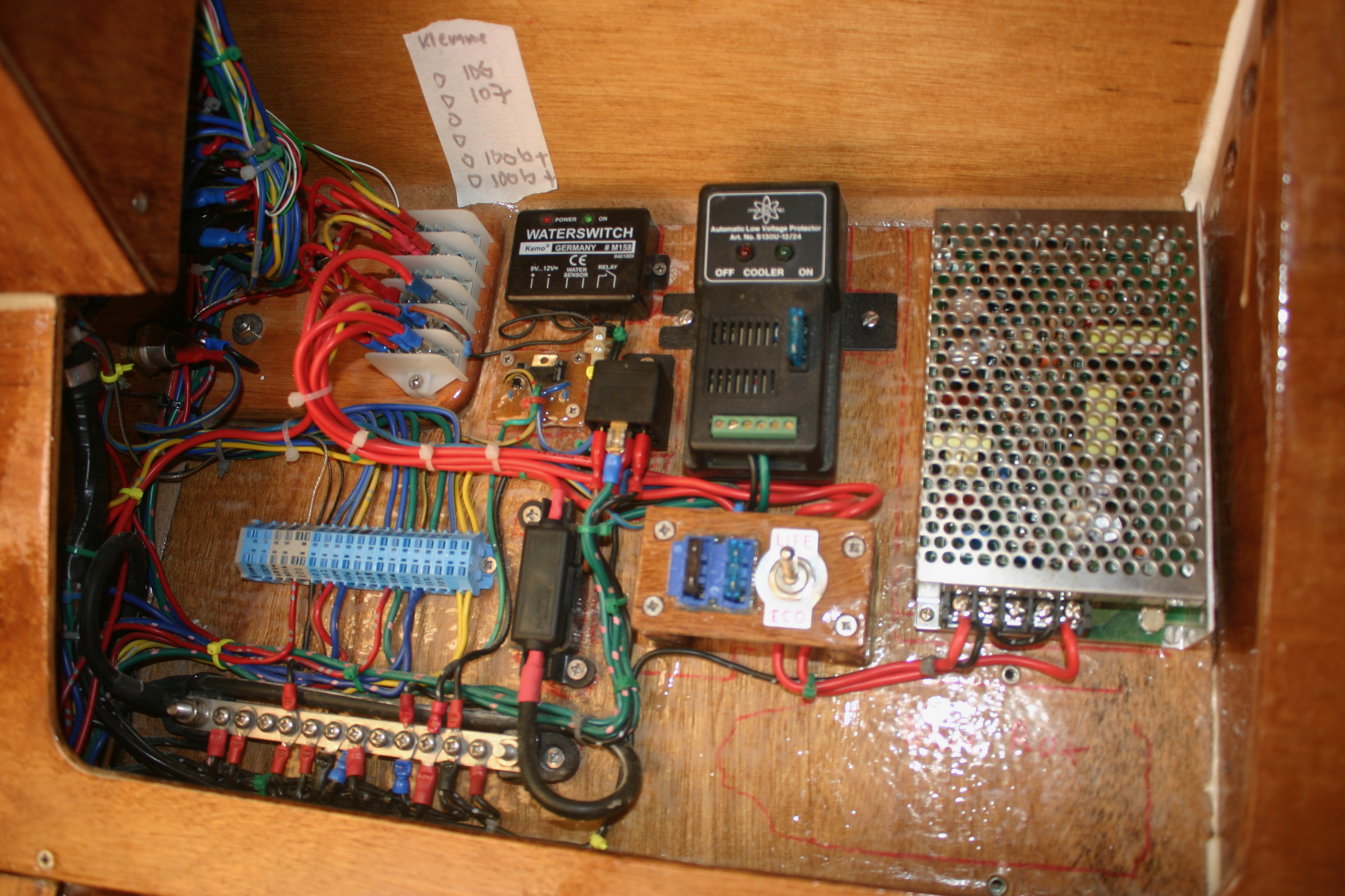
The Central Switchboard
Most electrical functions are controlled from the central switchboard in the port in the main bulkhead with the main connector borad just behind it in a small cabinet.

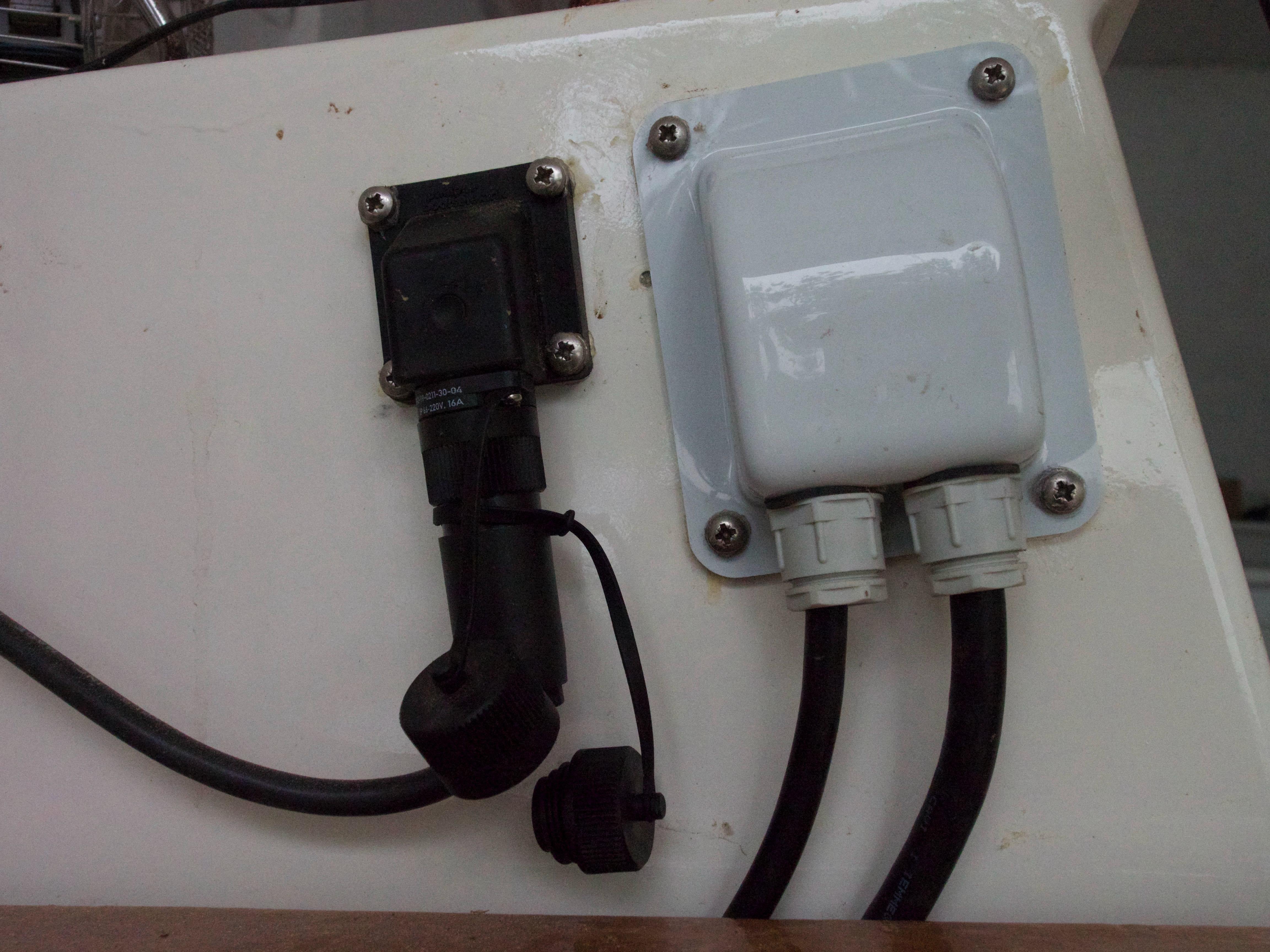
The Main Power Supply
The main power supply connectors are in another cabinet in the port hull companion hatchway.
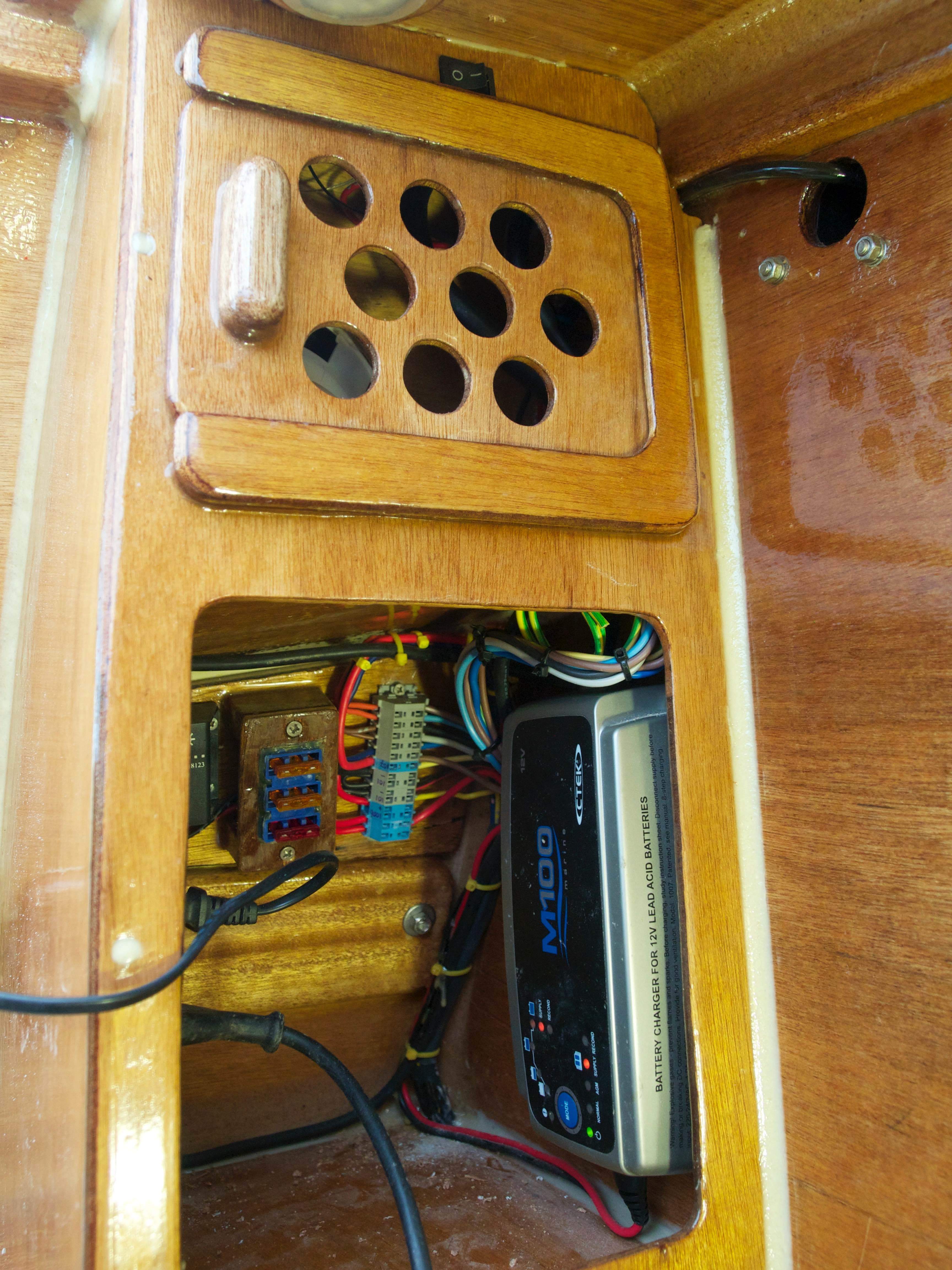
Connector Box in the Port Hull
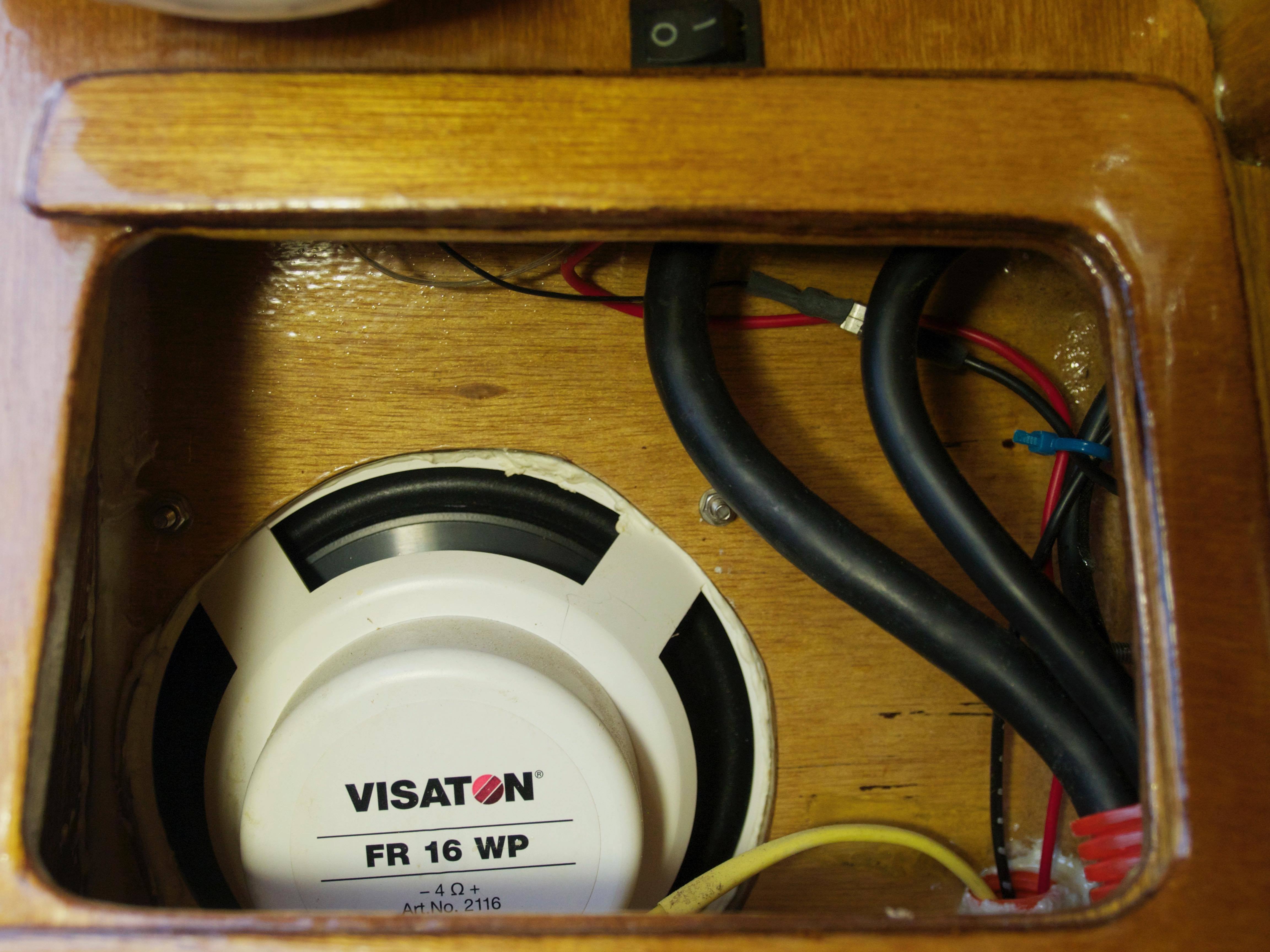
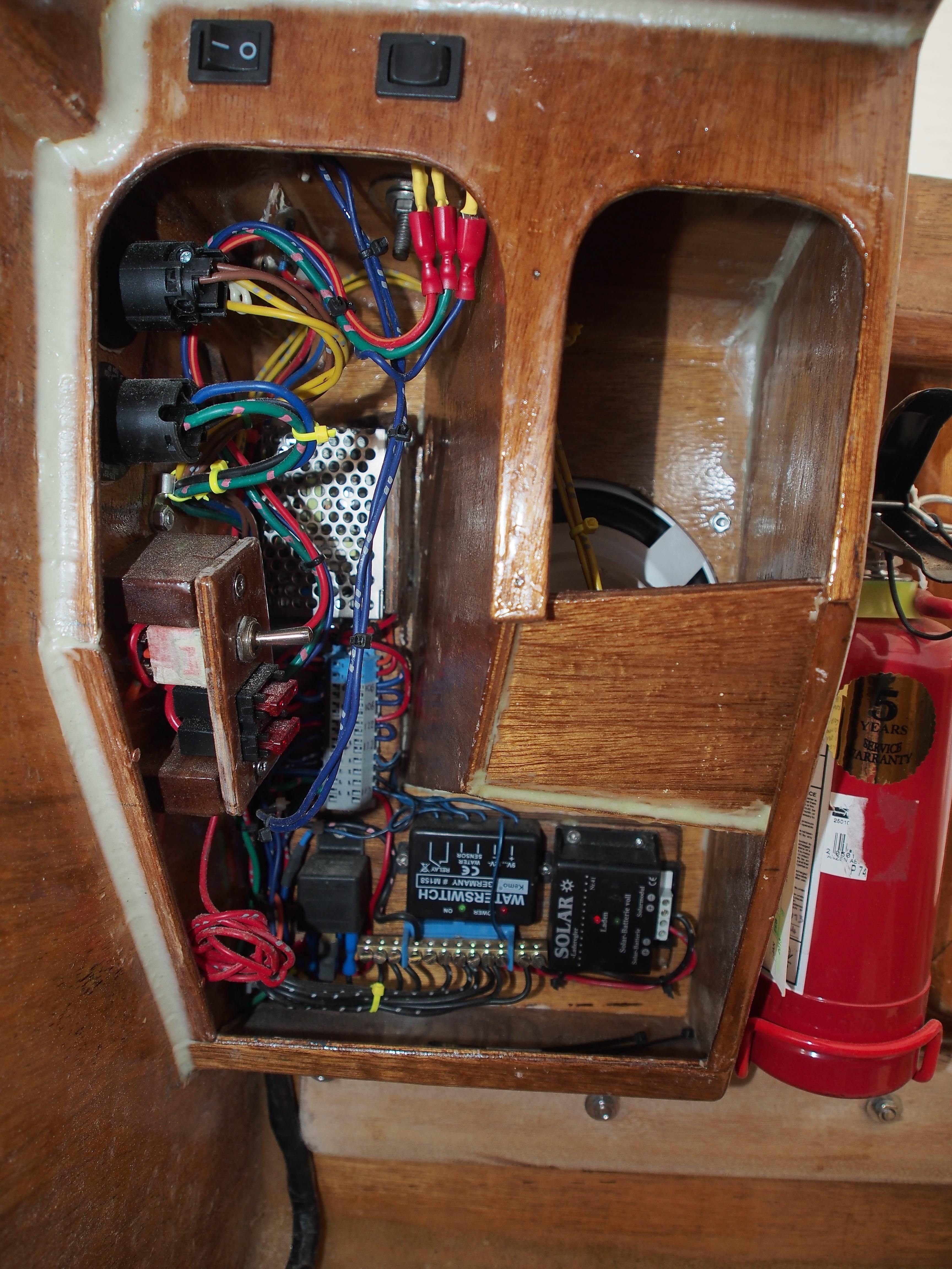
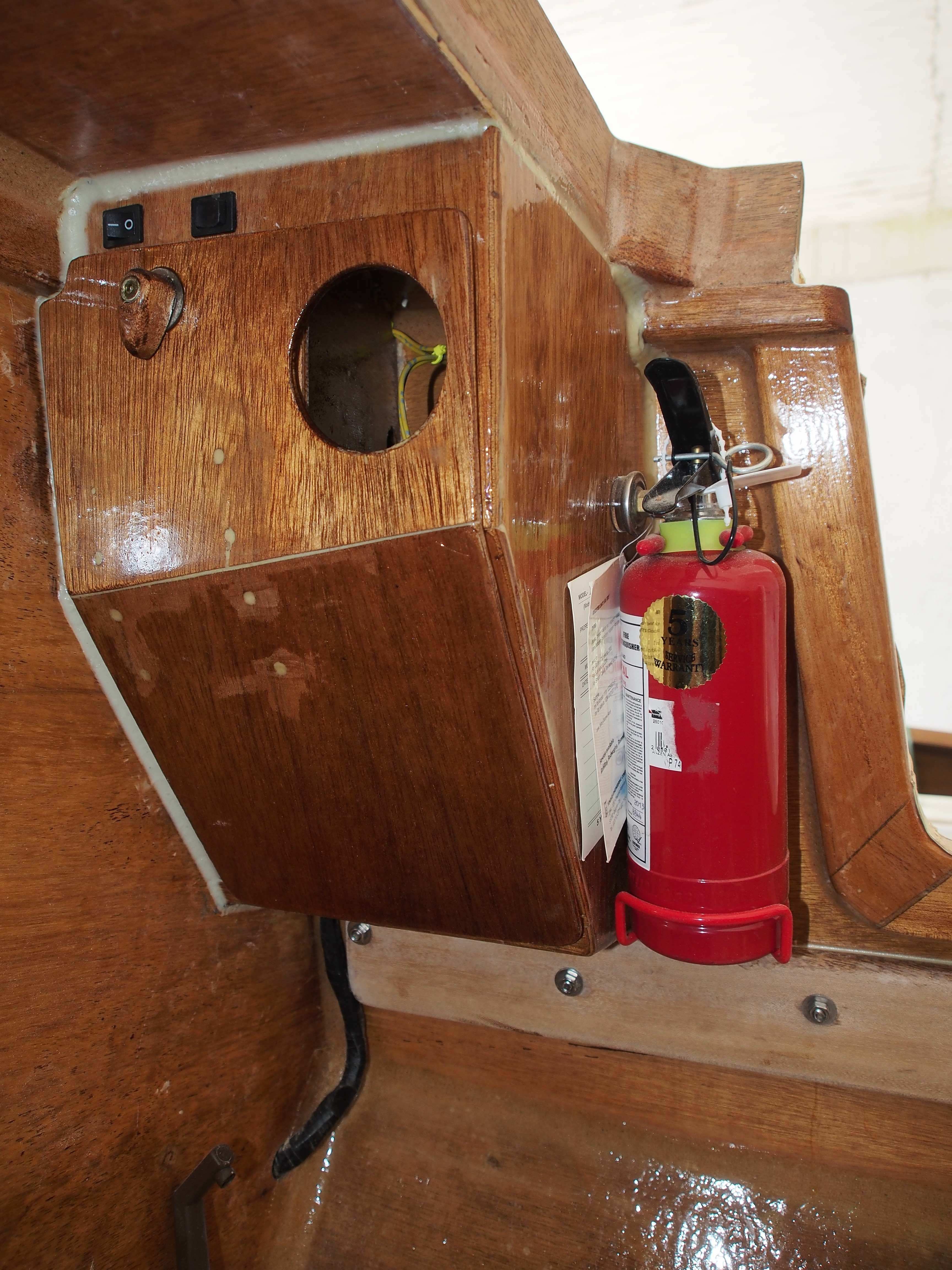
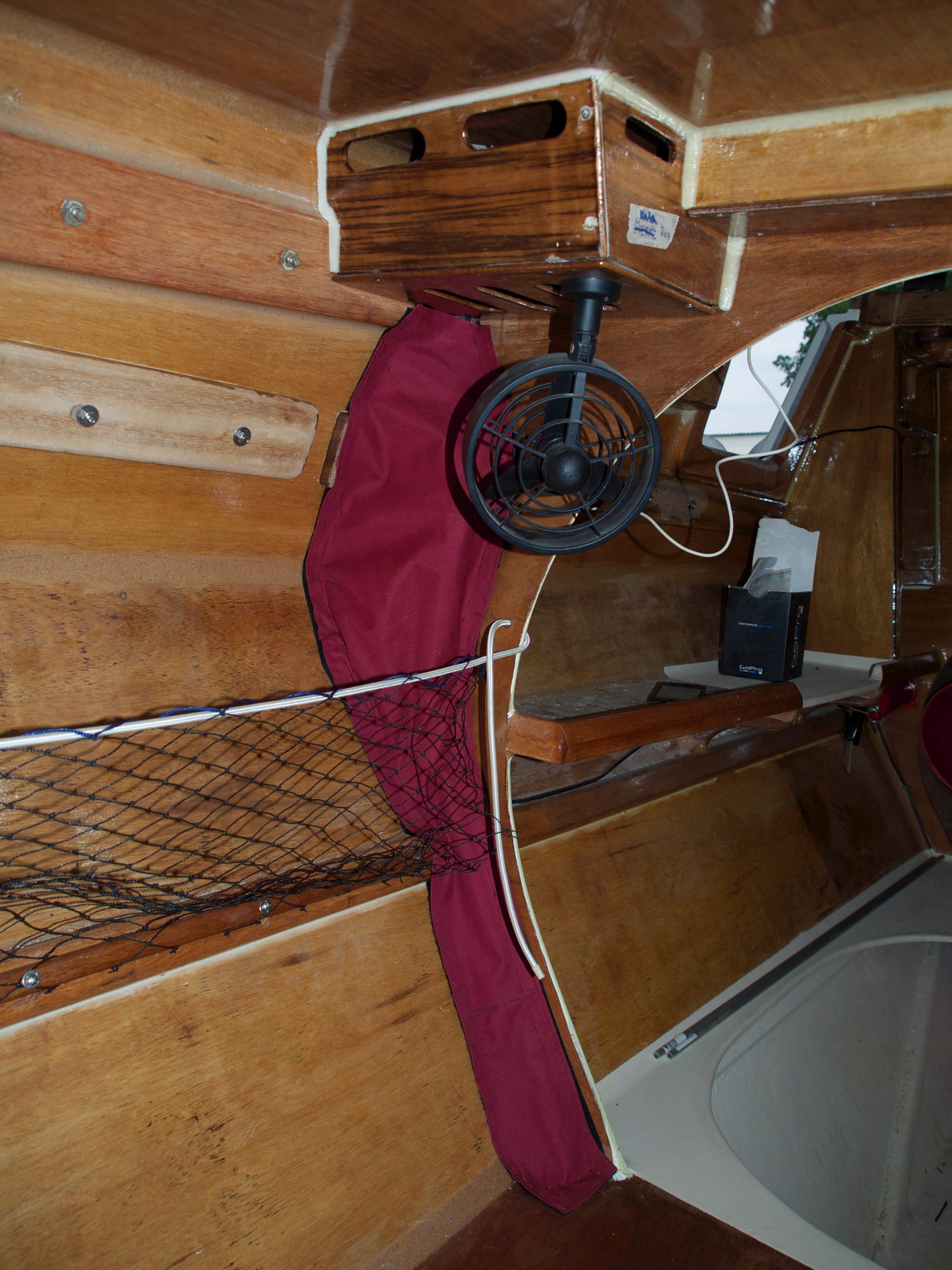
The starboard hull also contains a small cabinet at the compagnion hatchway that accommodates the connectors, solar battery charger, electronics for the starboard hull bilge pump and an LED power supply. A separate compartment contains the starboard hull cockpit speaker. This is equipped with a drainage hole exiting to the cockpit in case the speaker membrane gets damaged and water penetrates the compartment. At the top of the cabinet are the switches for cabin light and bilge pump.
Stereo
For music we are using a standard car radio which can be controlled by an Ipop or Iphone.
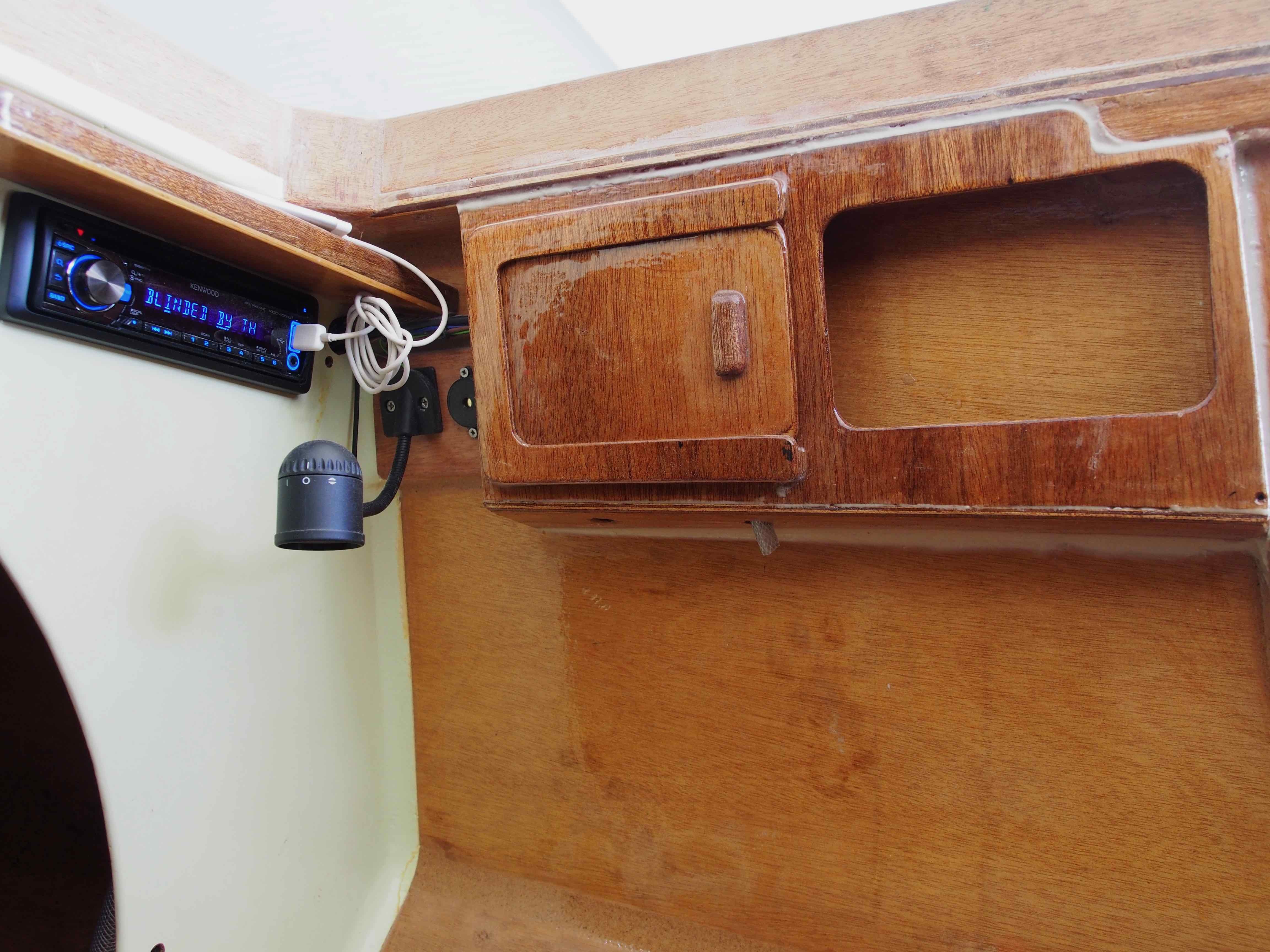
Right picture: back side of radio box with fan for cabin attached to it.
Connections
There are many connections for various purposes. Below are just some.


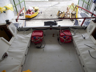
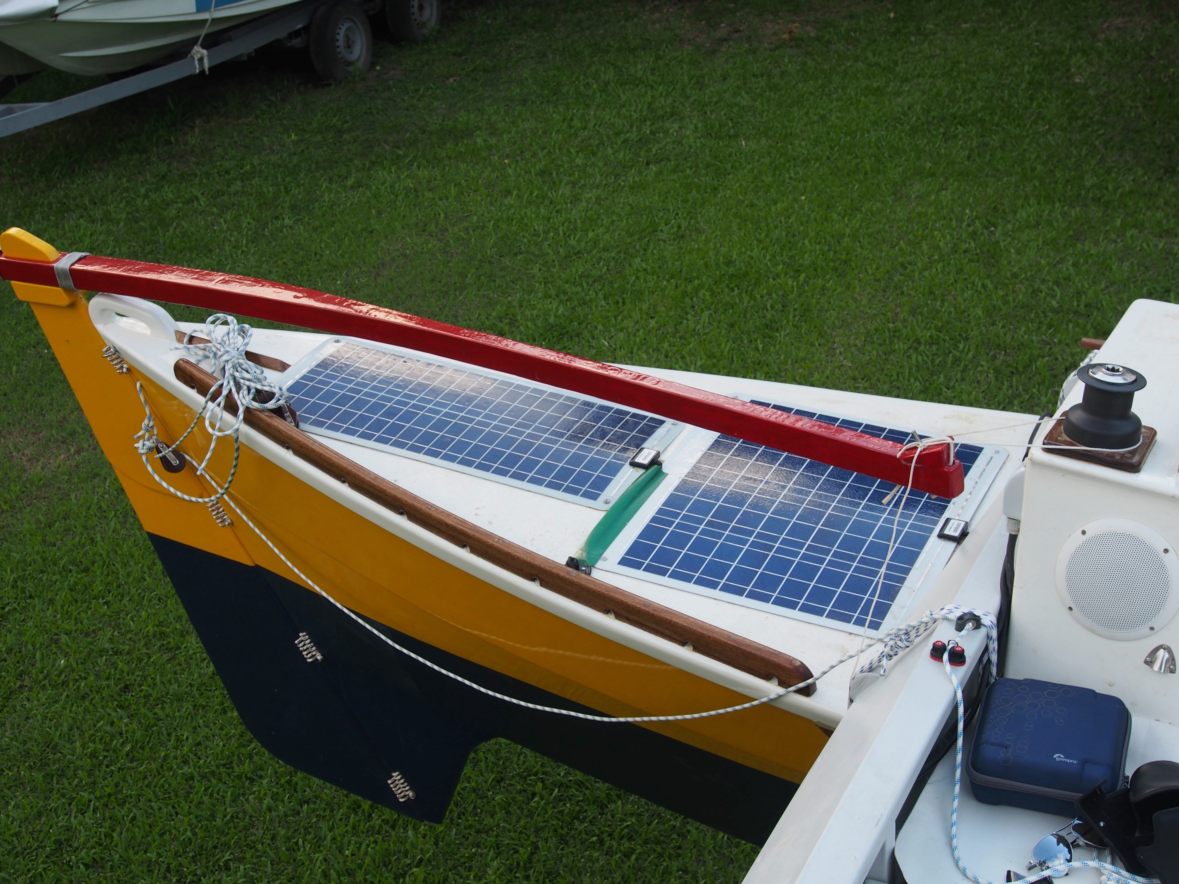
Power
Two 20 liter tanks for gasoline were fitted in the cockpit for the outboard motor fuel. For charging the battery, a total of three thin film solar panels (four planned) with 140W (180W) are glued onto the port sections of the hulls and connected via 4 individual solar chargers to the battery.
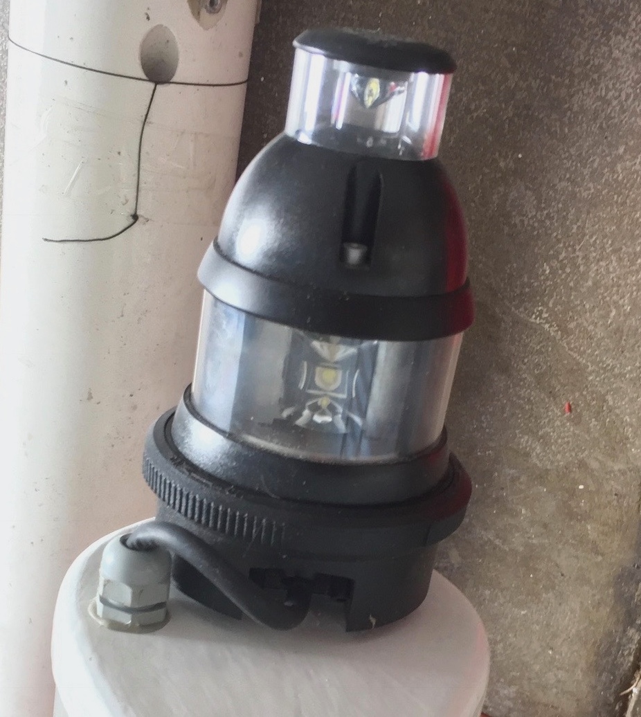
Navigation Lights
Complying with international regulations, which require for small boats only one three color light and an anchor light at the top of the mast, such dual function LED light was fitted at the mast top.
Battery and Main Switch
To start with a 40Ah AGM battery with 12V was installed in the central section of the port hull under the bed floor. A battery maom switch is in the bulkhead in the port hull too to totally disconnect the battery if needed.
Moving to Talisay
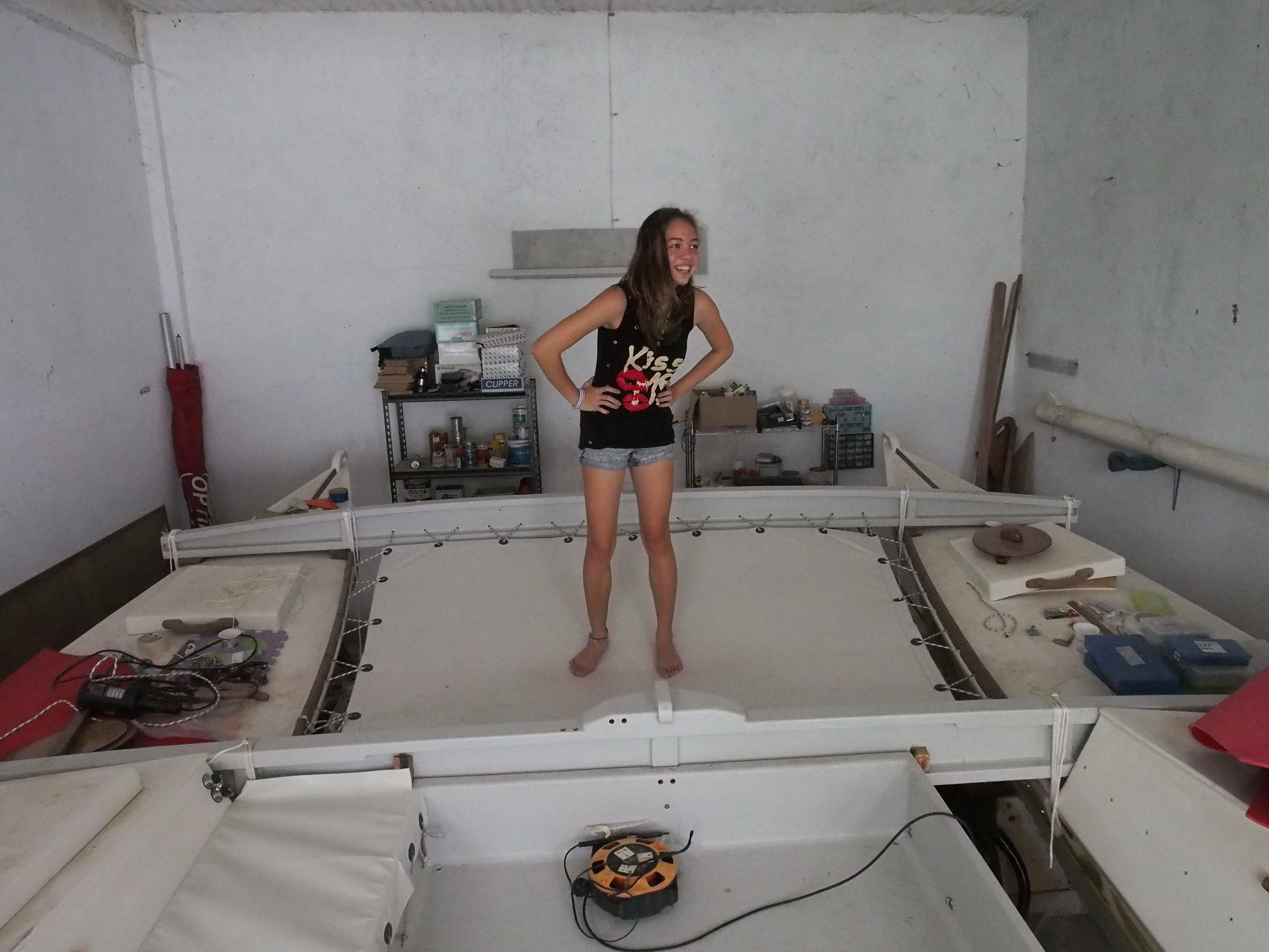
Once the major components were installed in the port hull, cables connected, charging cirquit and lights working, it was time to move the port hull to Talisay to start completing the boat. The electrical system of the starboard hull was installed in Talisay. After the electrical system in the port hull is completed we therefore moved the hull to our newly rented boathouse on Talisay. It has exactly the riht size to fit the assembled boat, has electricity and can be locked. So we can complete the building there without having to clean up and lock up tools each time we leave.
Magayon 2 also got company from Lemony. The little optimist will get some overhaul and some provisions for rowing so that she can be used as a dingi for Magayon 2.

We were really lucky to find the boat house at Walter’s place. It has just the right size so that the boat can be assembled inside. It is lockable and therefore it can be used as a workshop and the tools can be left lying around without getting legs. And ist protects from the climate. State of the art, quite rare here. The next step is to put some lighing and power outlets in there, the previous tennant had ripped everything out when he abandoned the place which he had used for a power boat.
Finishing the Interior of the Hulls
It took some time to come up with decisions about how much work to put into the interior. When sailing Magayon (1) we hardly used the cabin, basically because it was most of the time it was too hot.
Magayon 2 will have two sleeping places for six, four in the cabins and two in the cockpit. Only the two main bunks (called Captain and Guest 1) in the picture on the left will have thick mattraces. Bunks for Guest 2 and Guest 3 will have relatively thin mattraces that can be stowed away easily. If sleeping space in the cockpit for two additional guests are needed camping mattraces can be used.

The port hull will be the command center with all the major electrics installed here.
The central switchboard, navigation table and log and depth sounder will be here. It also has a Ipod controlled car radio.
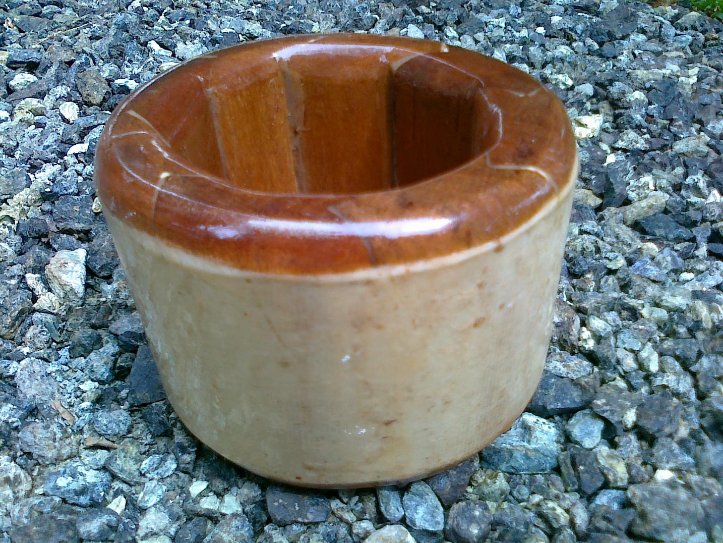
The port hull will have a simple bucket toilet.
Both hulls have two speakers each, wired crosswise so that there is a stereo effect in each hull but also in the cockpit.
The starboard hull will have a 120l fresh water tank with pump and faucet for drinking water and cooking. It will also have a single flame alcohol cook stove, some basic electrics for lights, power outlets and for the bilge pump.

To be continued…
The Cockpit and Outboard Motor Bracket
The Cockpit
After long delays caused by an accident we finally started working on the cockpit. A couple of month ago we found a supplyer of Toughply in Manila, a better quality plywood than the other brands available in Laguna. Toughply with 6mm thickness has 5 layers while the ordinary plywoods with 6mm thickness have only 3 layers.
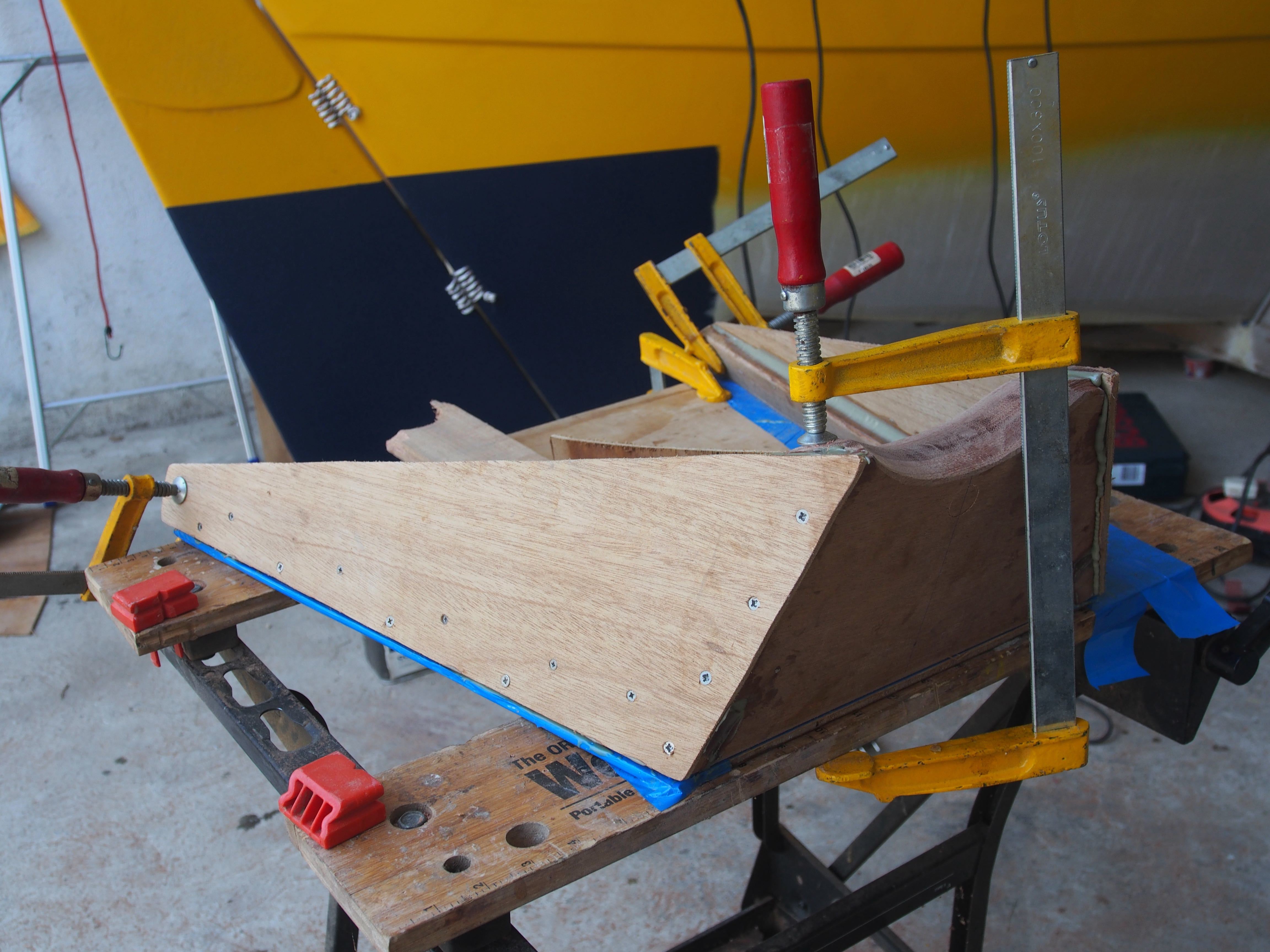
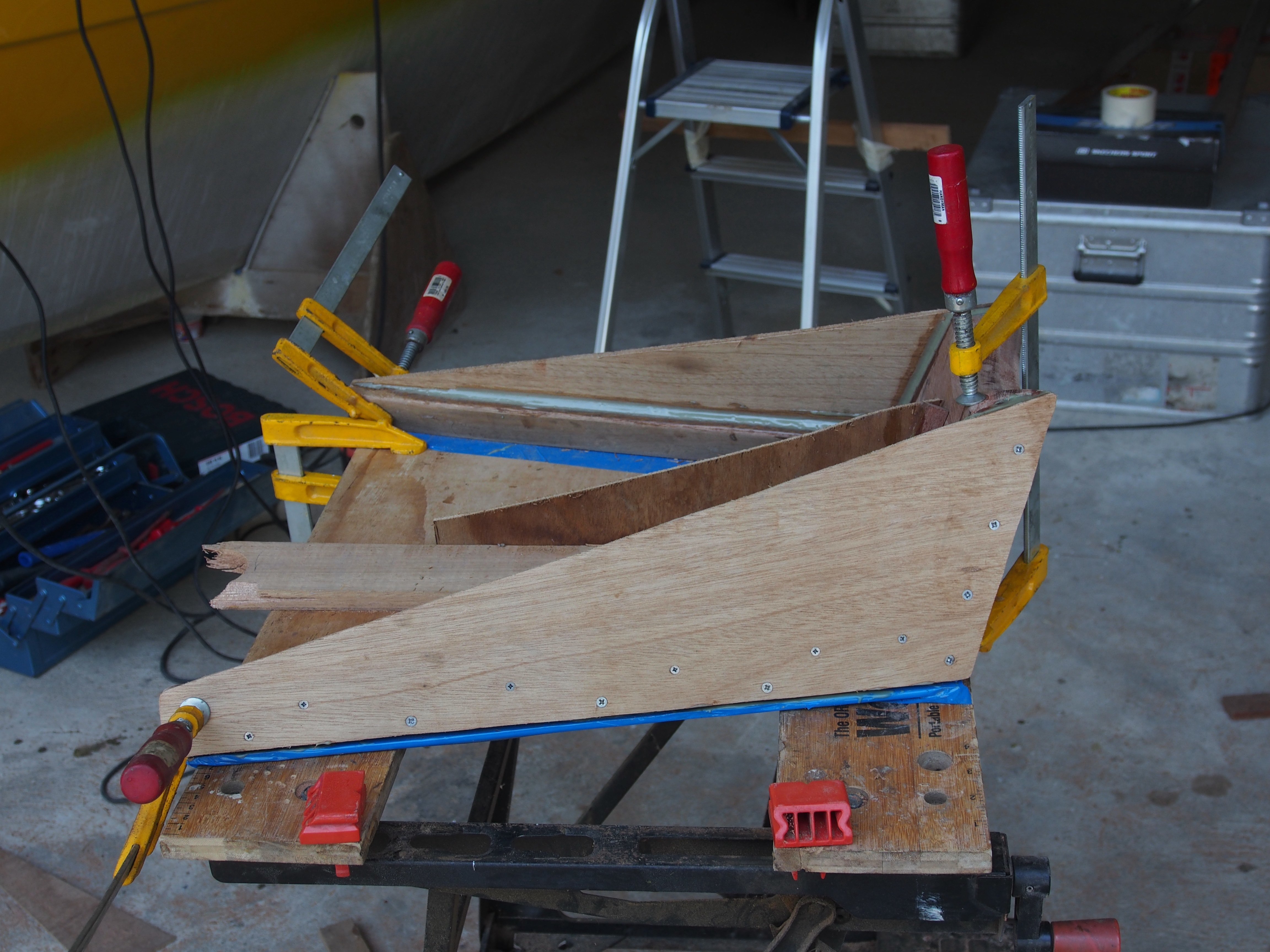
 |  |
| The raw cockpit under construction | Cockpit and bow cross beam |
The cockpit has the size ofa full plywood board, 8’x5’or 2.44m x 1.22m. Enough for two people to sleep in it if needed. Many builders modify the cockpit to accommodate boxes and plywood seats. We decided to stick to the original design for simplicity and to minimize weight.
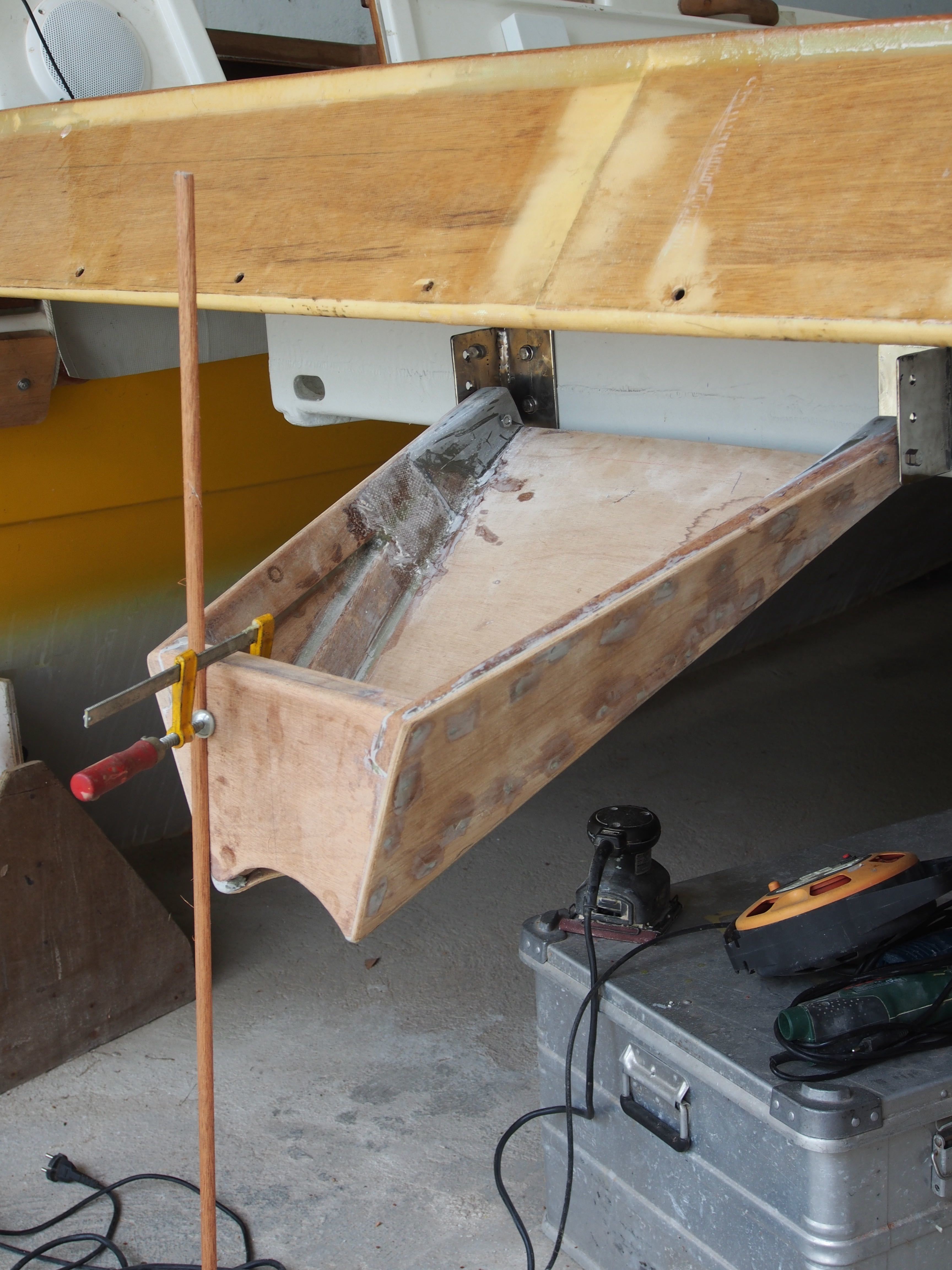
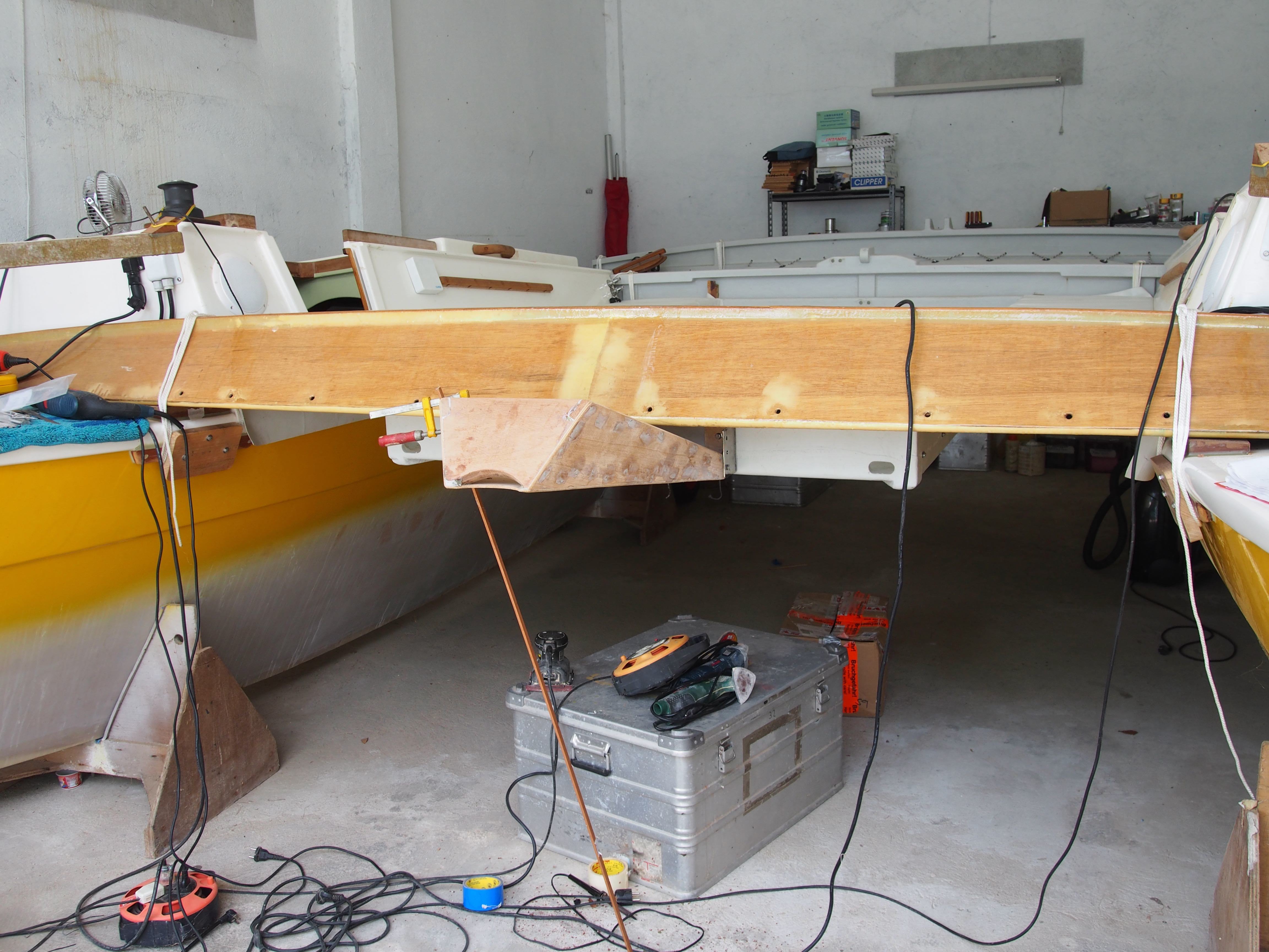
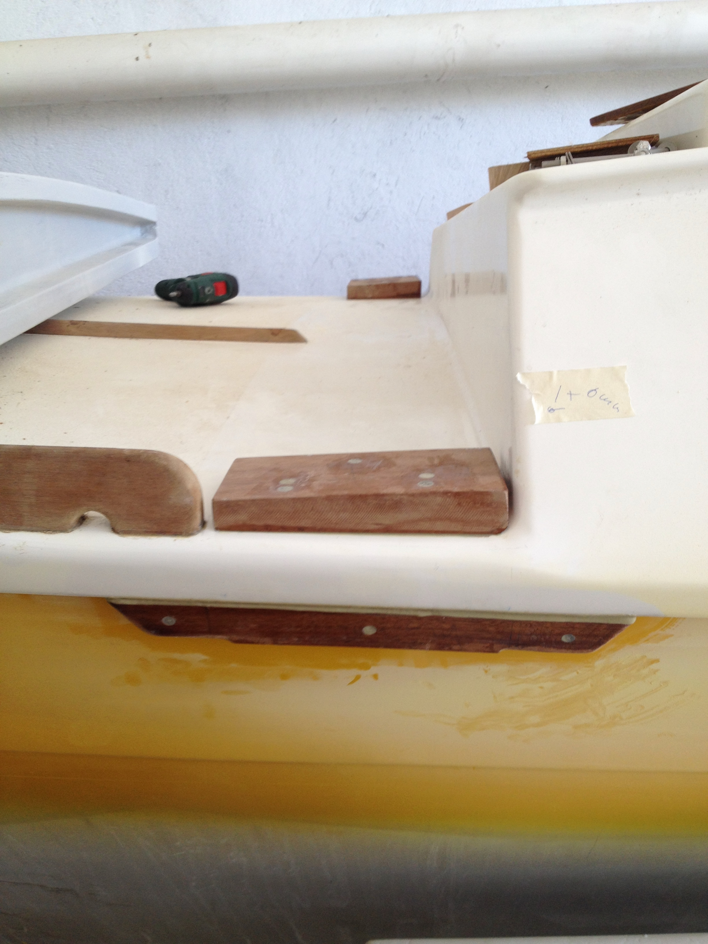
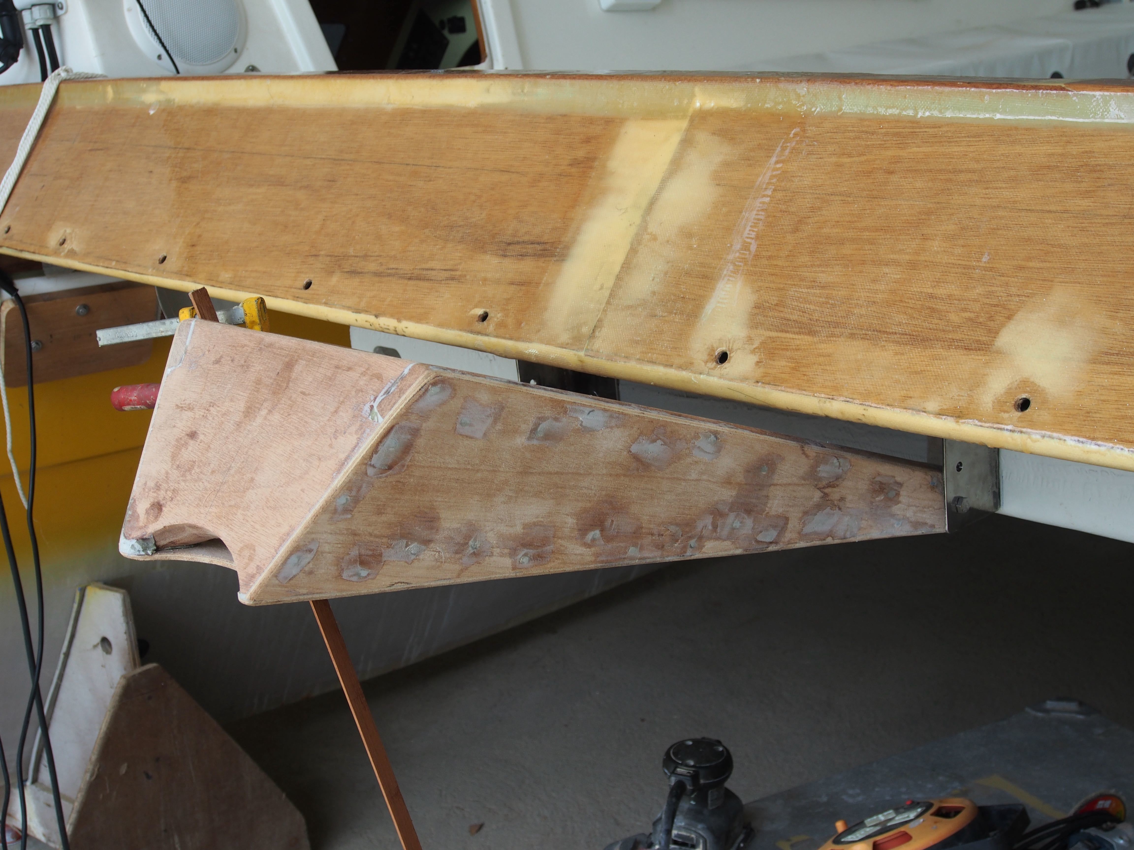
The Outboard Motor Bracket
The Wharram plans contain two options, the first included a outboard motor bracket that is mounted at the back of the cockpit and can be raised or lowered. In the second option the outboard motor is mounted on a backet underneath the cockpit. The second option takes away a big part of the cockpit space so we went for the first one.
17-18 May 2014
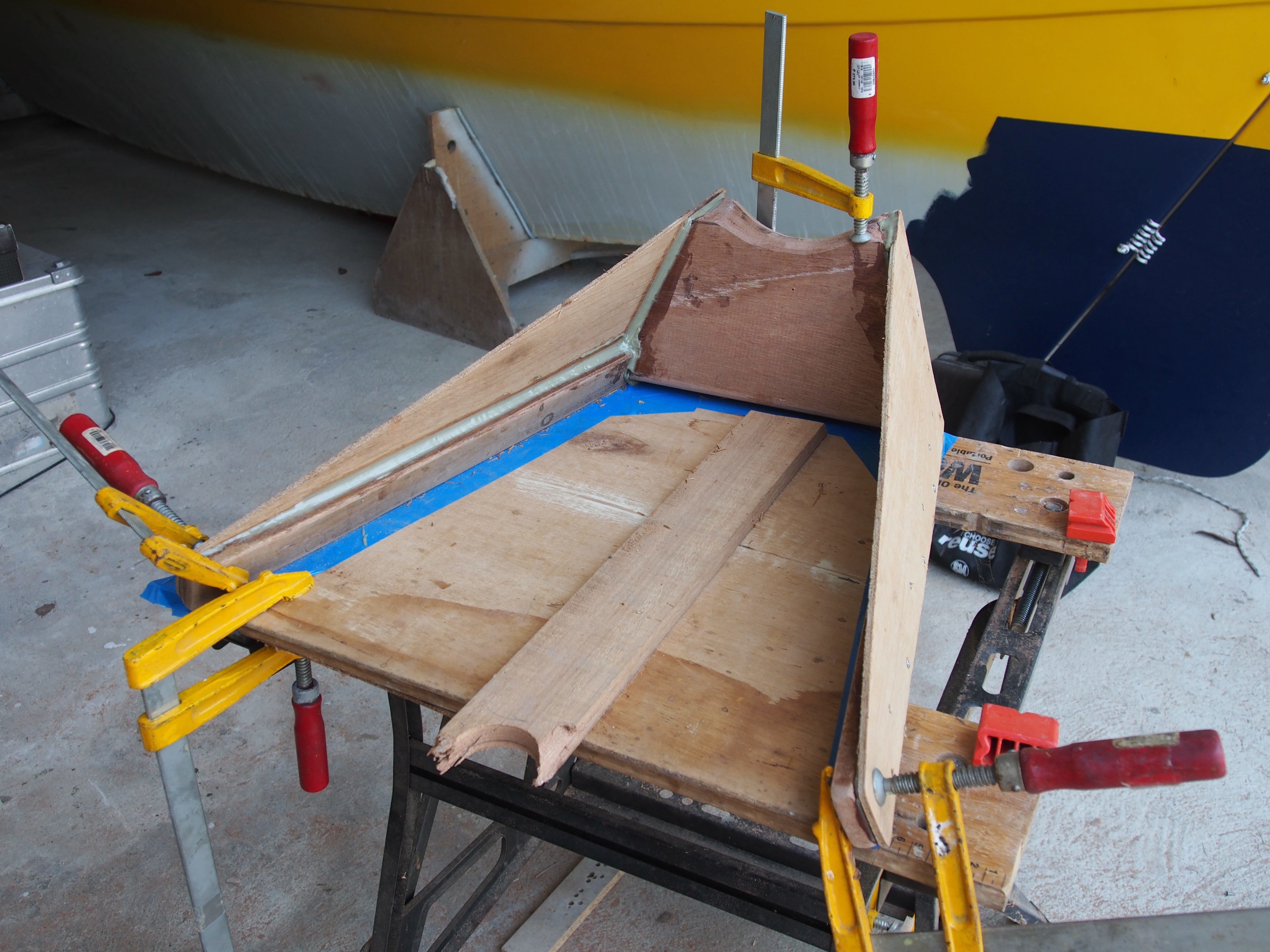
Finally I was able to borrow Matty’s 8hp Yamaha Longshaft outboard motor, exactly the size needed for Magayon. I needed a motor because the bracket is not drawn in detail in the plan, it just says to “..fit it to the outboard motor used..” It took the whole morning of Saturday to position the outboard motor on a frame made from the Black & Decker workbench and various wood pieces at the back of the aft cross beam and play around with the ideal position in raised mode. I could then measure the required length of the bracket, it should be as short as possible because shorter means sturdier. On the other hand, the motor should not get in the way of the tiller when it is in raised position. After determining the length and making the mounting board from three layers of hard wood, I cut a pattern representing the top of the bracket from 5mm plywood, which would also serve as the basis of a simple building frame. This I connected this temporarilywith duct tape (quote Miles from Lost when fixing an airplane suspension: “I don’t belive in much but I do believe in duct tape.”) to the cockpit and then determined the right angle for lowered position (this is one of two measurements in the plans). Then I made anohter pattern for the right angle of the mounting board. I then assembled the whole bracket on this patterns.
22 June 2014
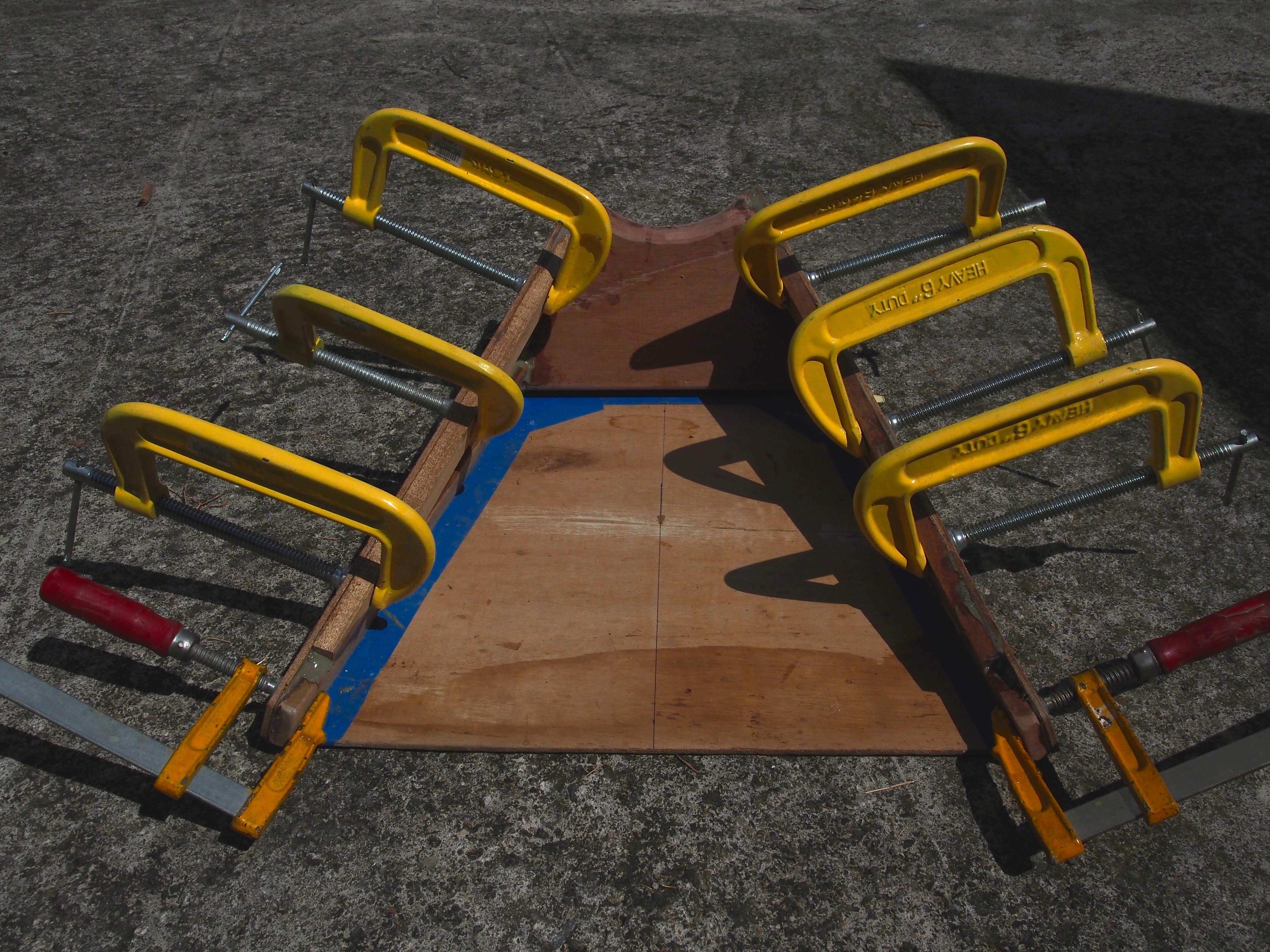
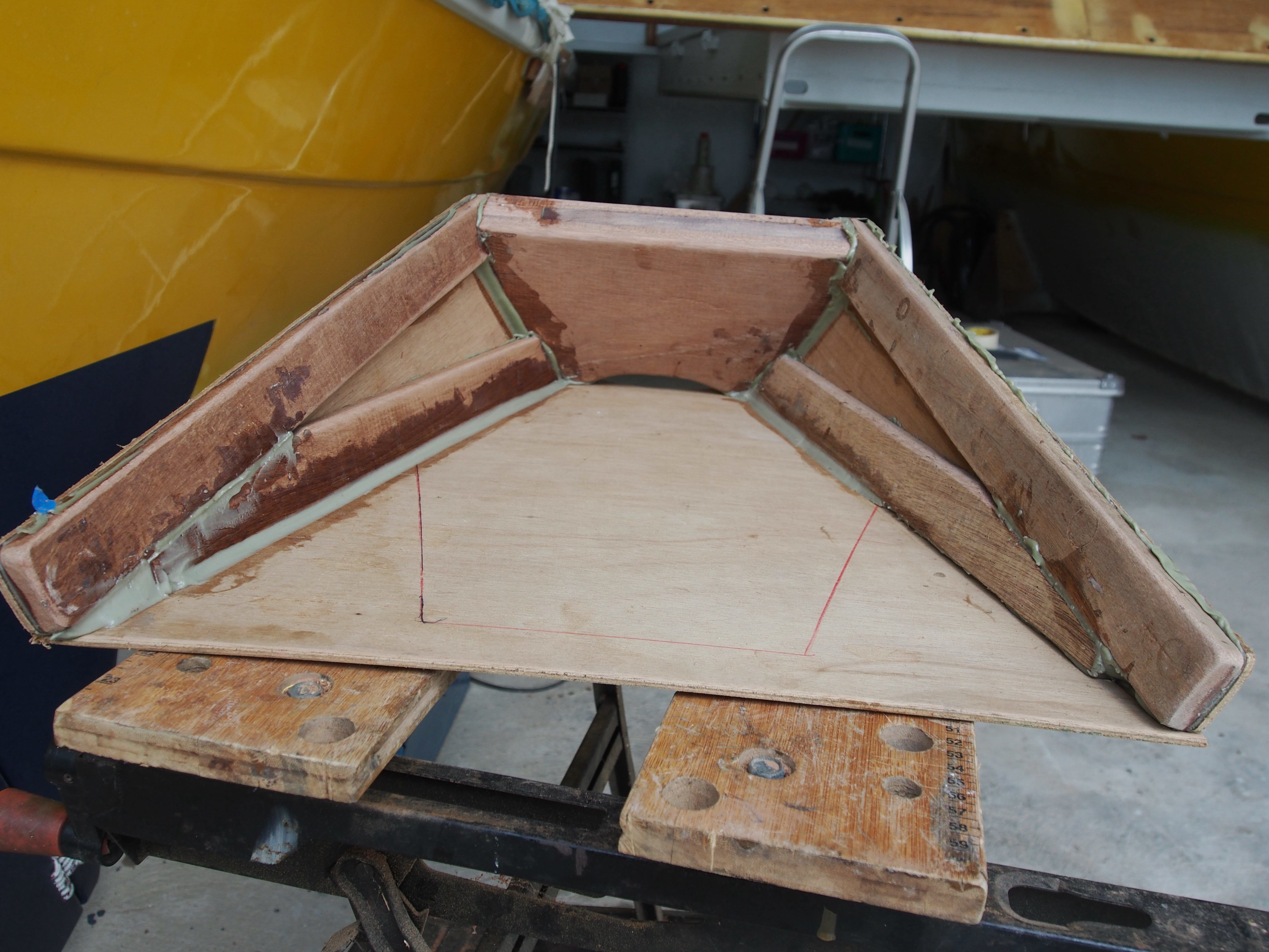
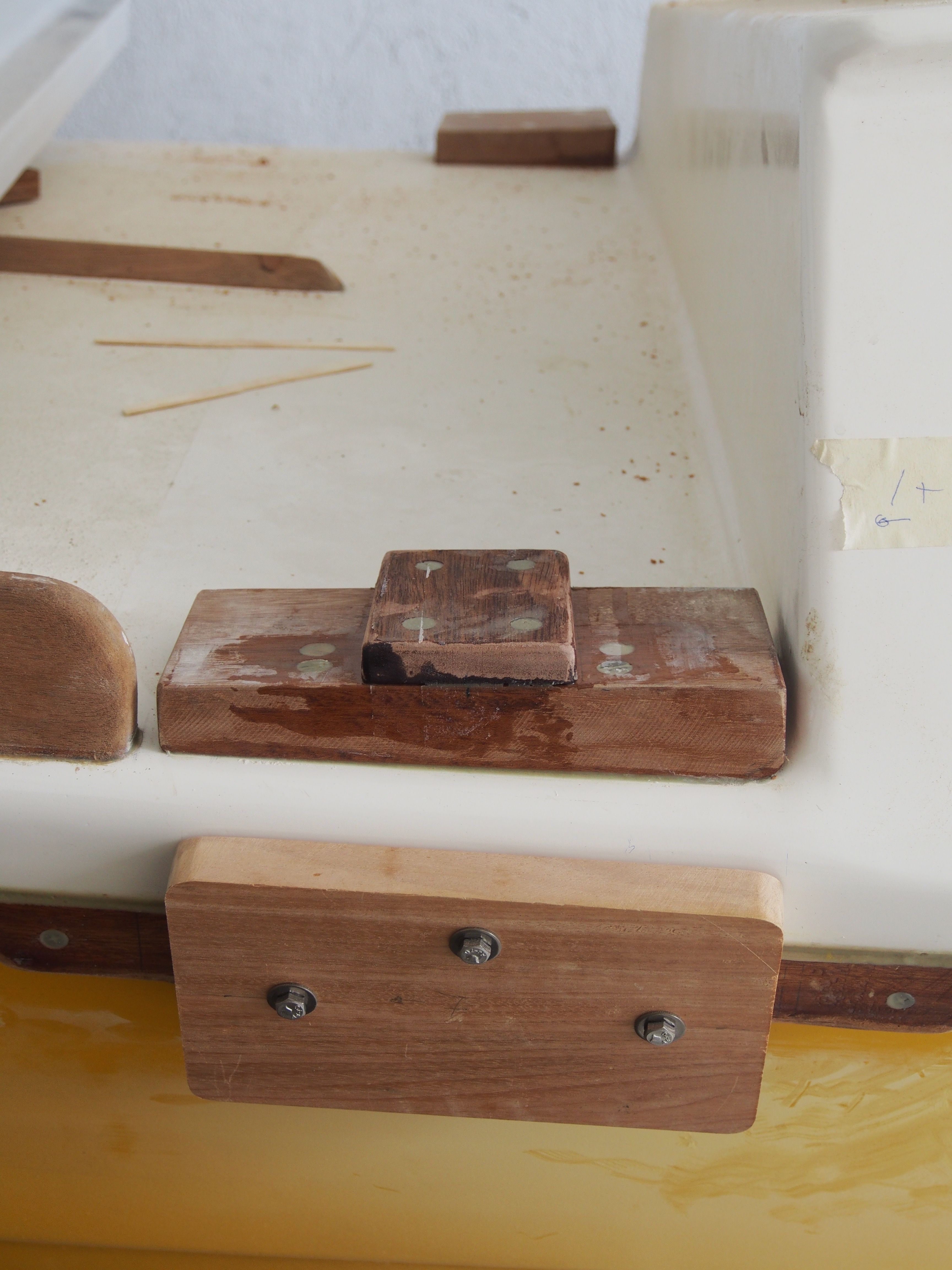
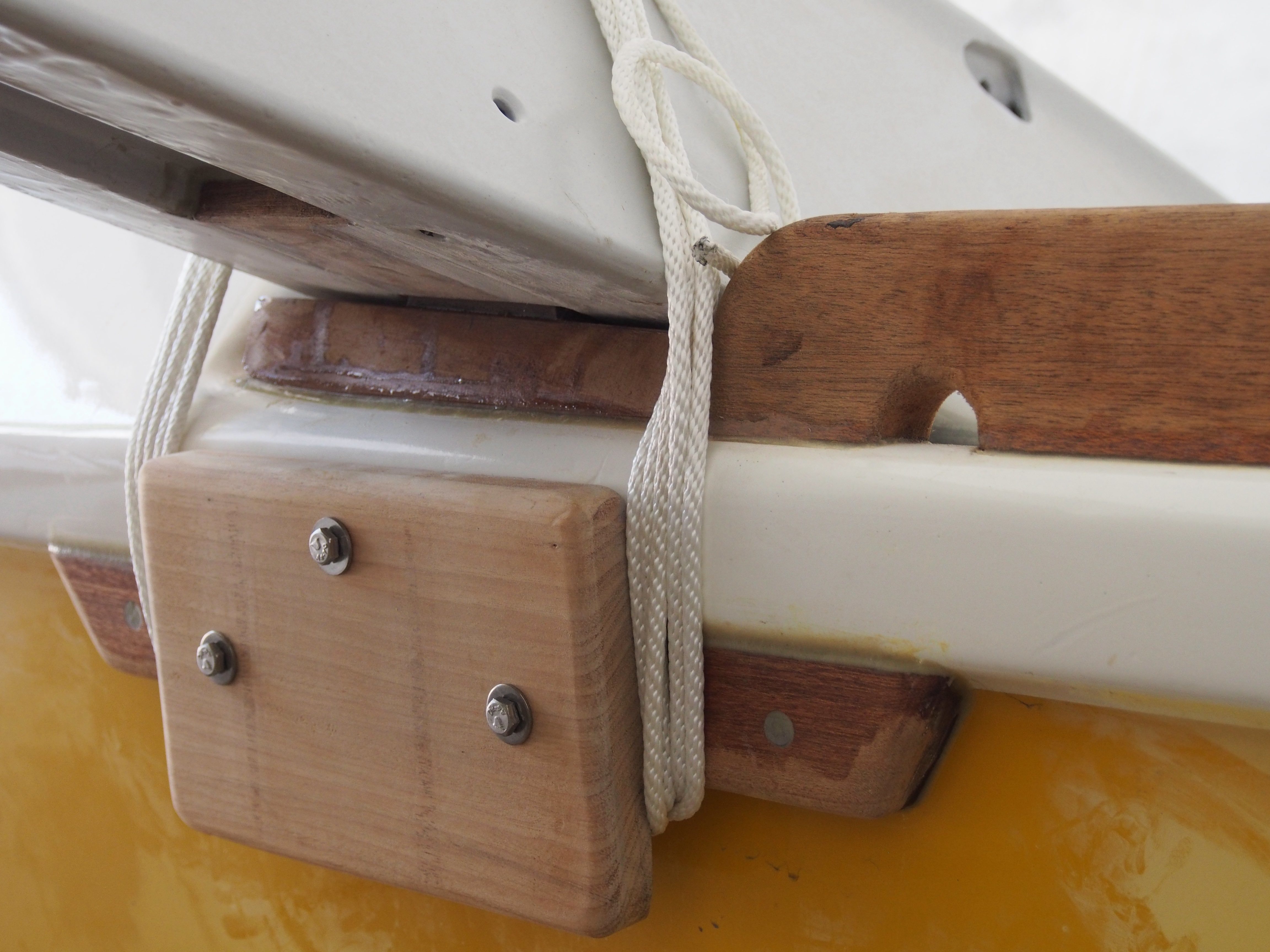
Finally finished the raw constuction of the outboard motor bracket. The ends which will bear the screws for attaching the bracket to the cockpit got some serious enforcements with epoxy mixed with milled fiberglass on the inside and the outsides were planed so that they provide parallel surfaces.
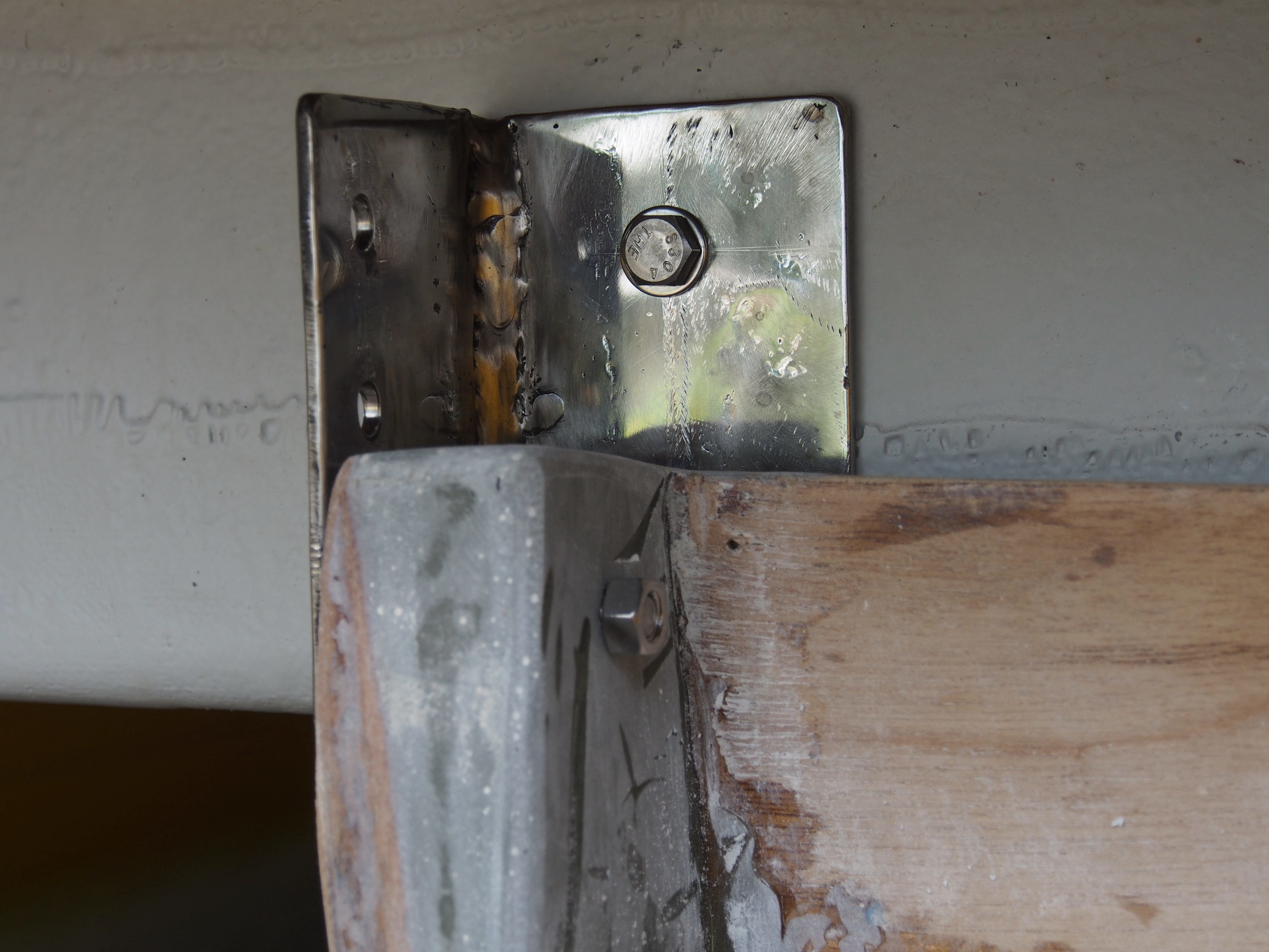

After unsuccessfully looking for some stainless steel angles in the local hardware shops I asked Eugene, the maker of the trailer, to custom make me some angles. They were done within a day and I could finally work on the mount of the bracket. The first step was to drill holes to size to test mount the bracket (see pictures above). The holes were then expanded to fill them with Epoxy fillets and filled with epoxy mixed with milled fiber glass.
I took the backet home to re-inforce it with fiberglass until the next weekend when the mounts will be finished.
Rudders and Tillers
Rudders
The rudders were some of the first parts cut out of plywood and then glued together. And the some of the last parts to be finished and mounted to the hulls.
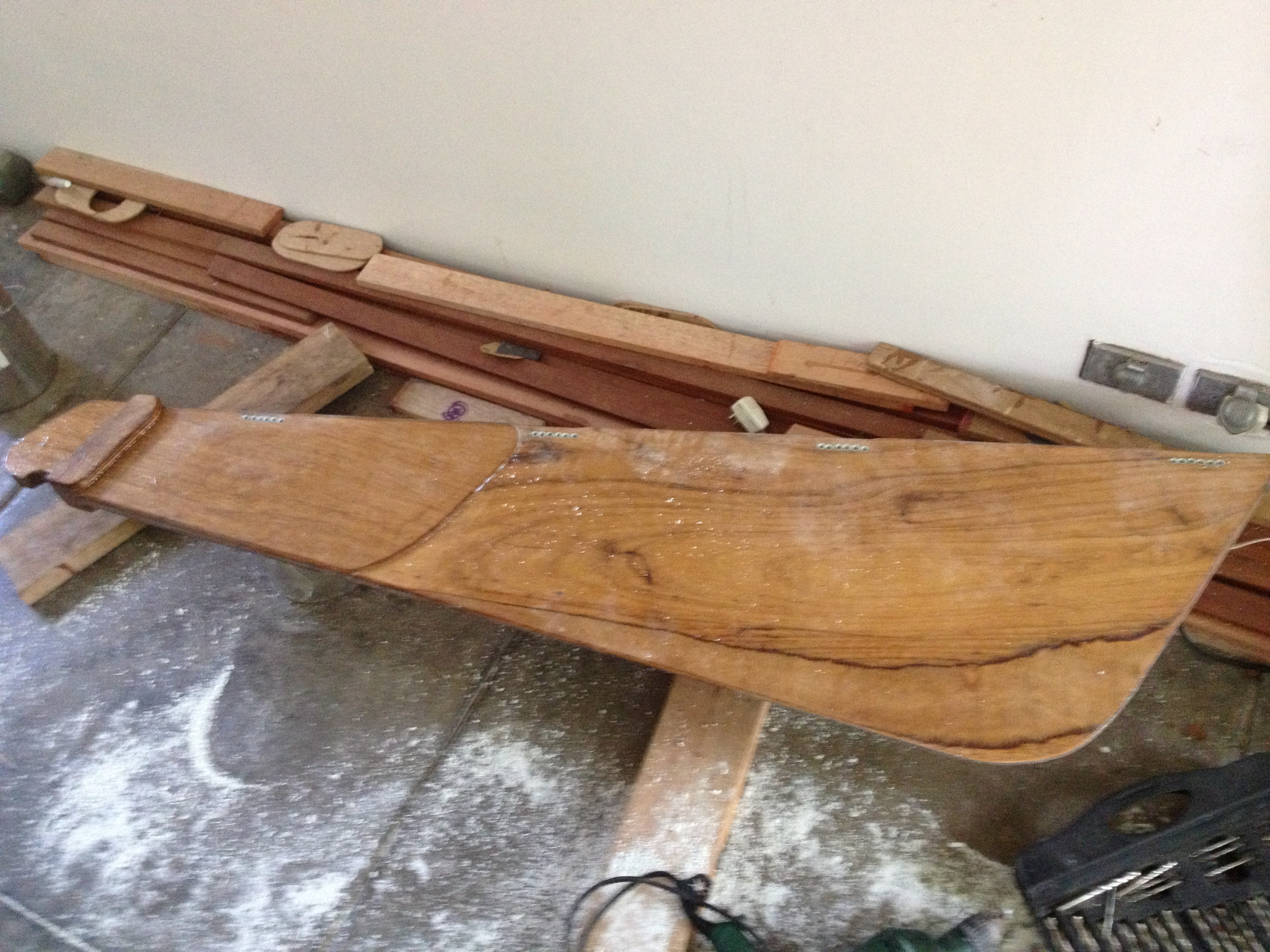
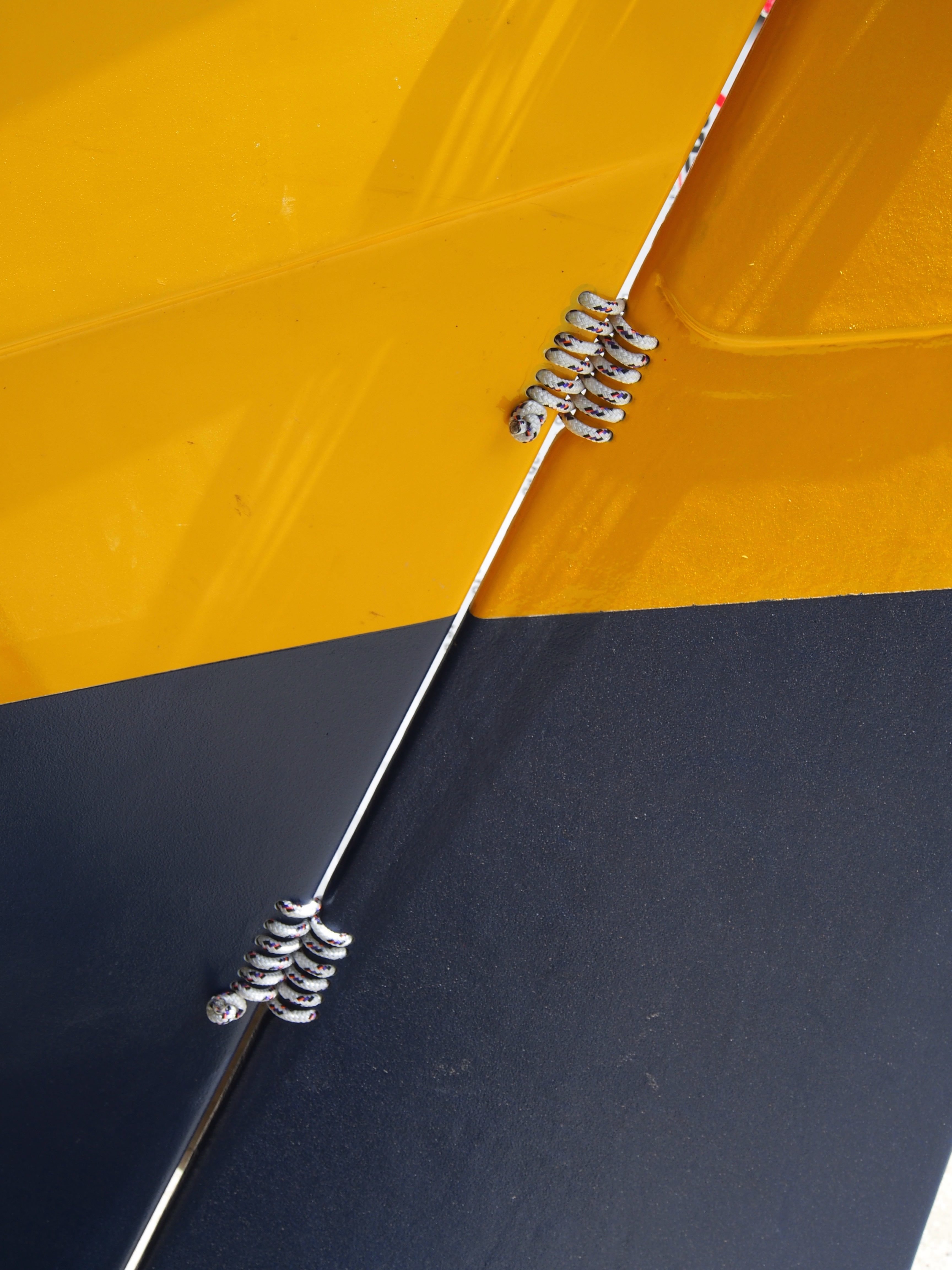
Finally they were mounted on the hulls in January 2014 and in April 2014 (port). The simplicity of the rudder hinges made from rope caught a lot of attention from the frequent visitors passing by at the construction site.
The hinges were done using ropes, Wharram style. The big advantages are the use of local materials, no corrosion and the ability to replace / fix them easily.

Tillers
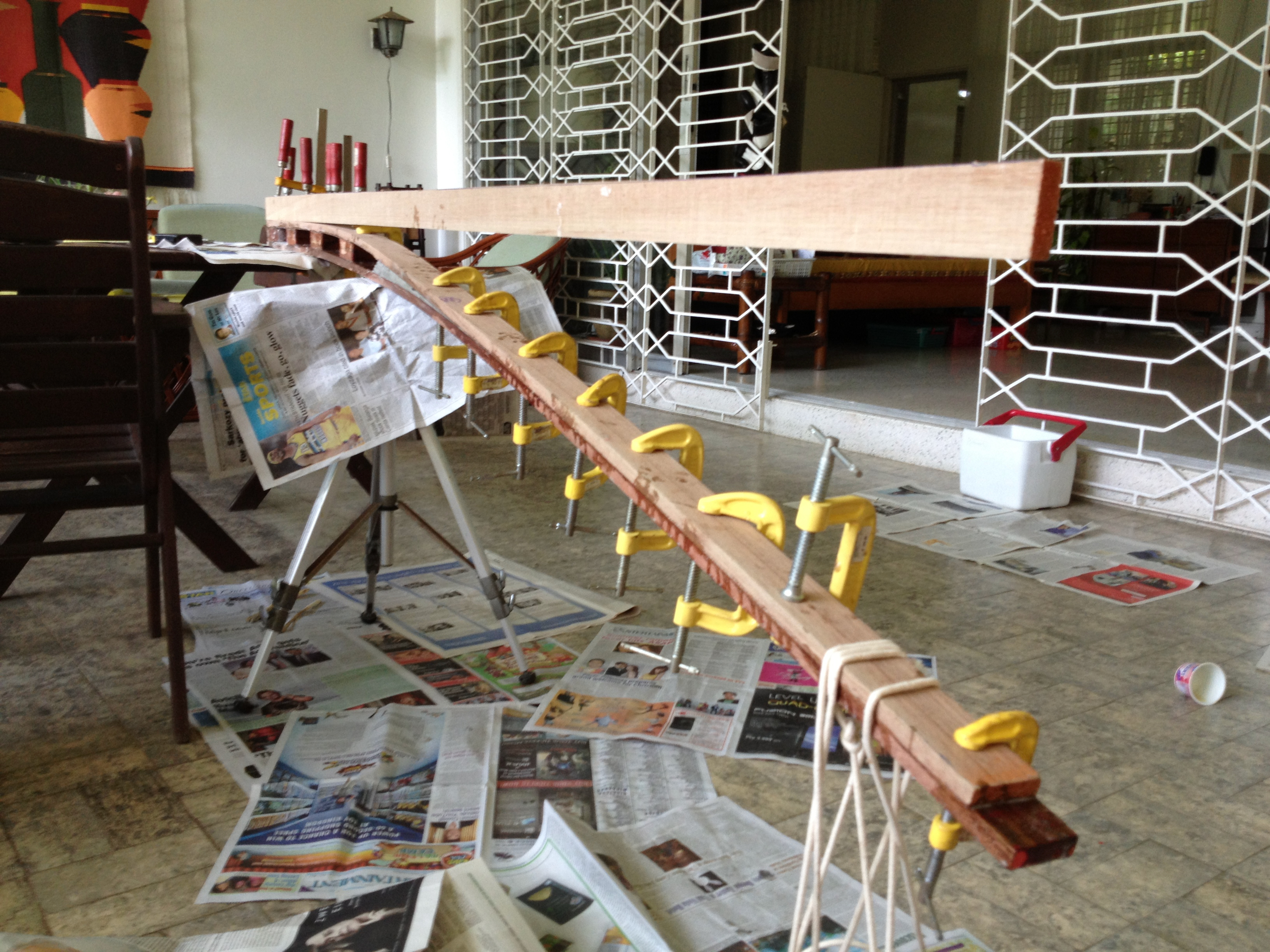
I really wondered whether we could get the bent shape of the tiller without breaking the wood. When we had built Lemony several of the battens had broken. But it bending the wood turned out to be easy. Anohter problem was that you can’t buy full sized wood here. You buy a batten, say 1″x 2″, but that is the measurement after the saw mill. Then they plane at least two edges so that in fact the actual measurement is smaller, e.g. 3/4″ x 1.3/4″. Where I come from this would be considered cheating, but that’s how it is here and there is nothing once can do about it. The alternative would be to buy oversized wood and plane it to the final dimensions, a lot of planing to do. So we decided to use undersized wood and strengthen it with 3 layers of fiberglass to compensate for the lower strength.
The basic construction
The tillers are bent inwards to ensure optimum angle of the rudders, pretty much like the front wheels in a car. The inner side in a curve has a smaller radius then outer side, so the inner rudder needs to fold in more than the outer one. To get the right bend, two strips of wood are bend and then glued together.
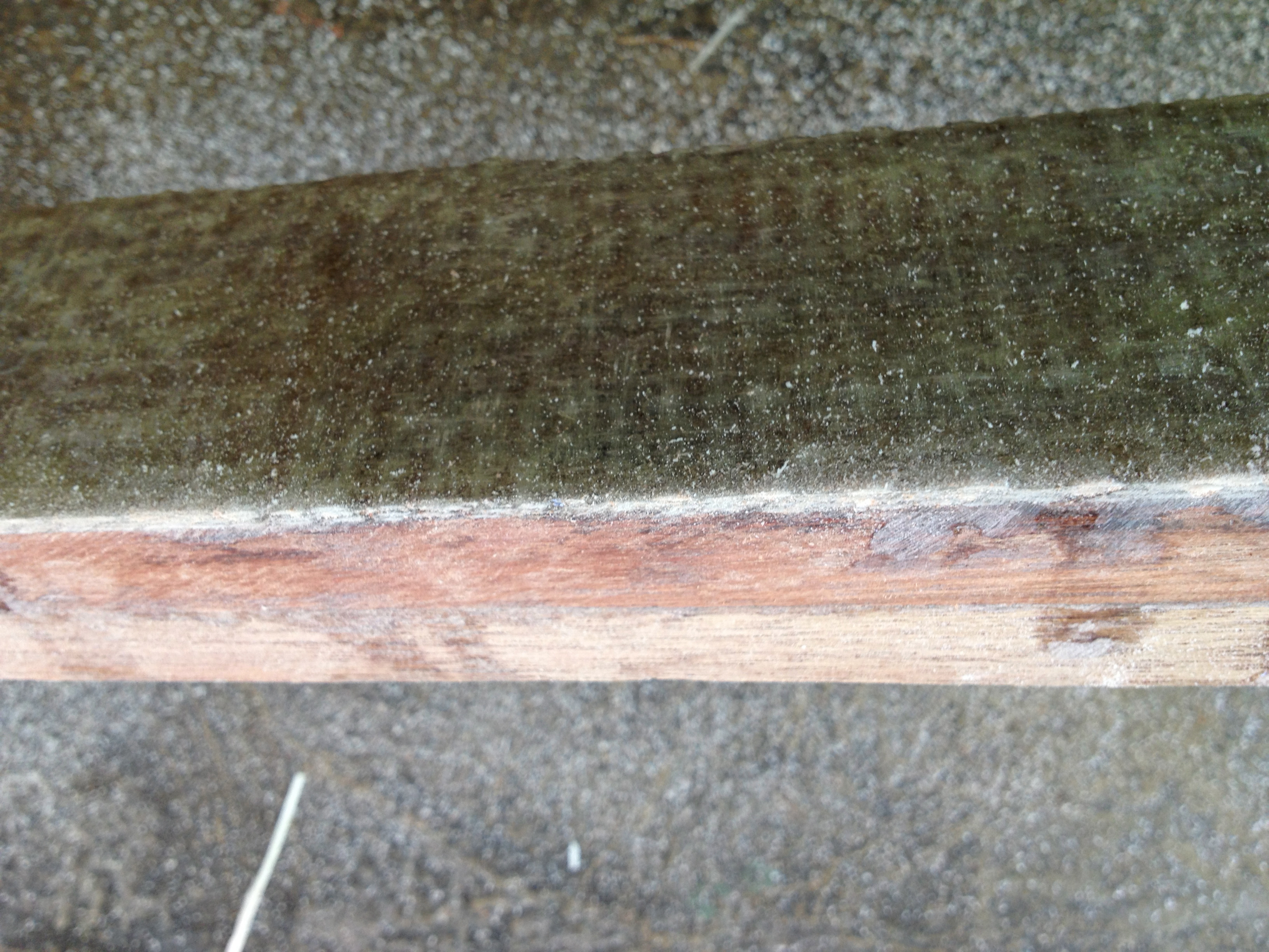
Reinforcements
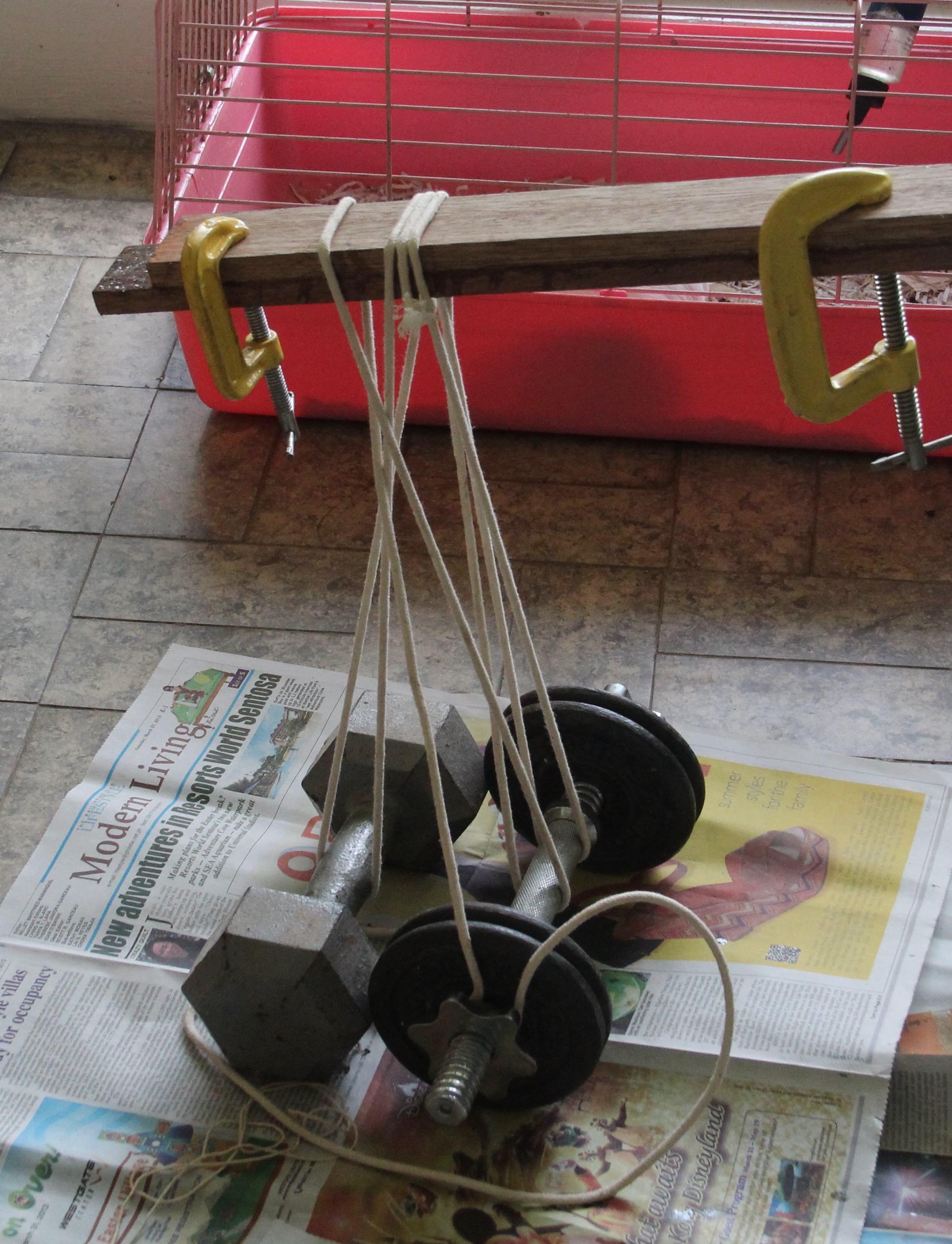
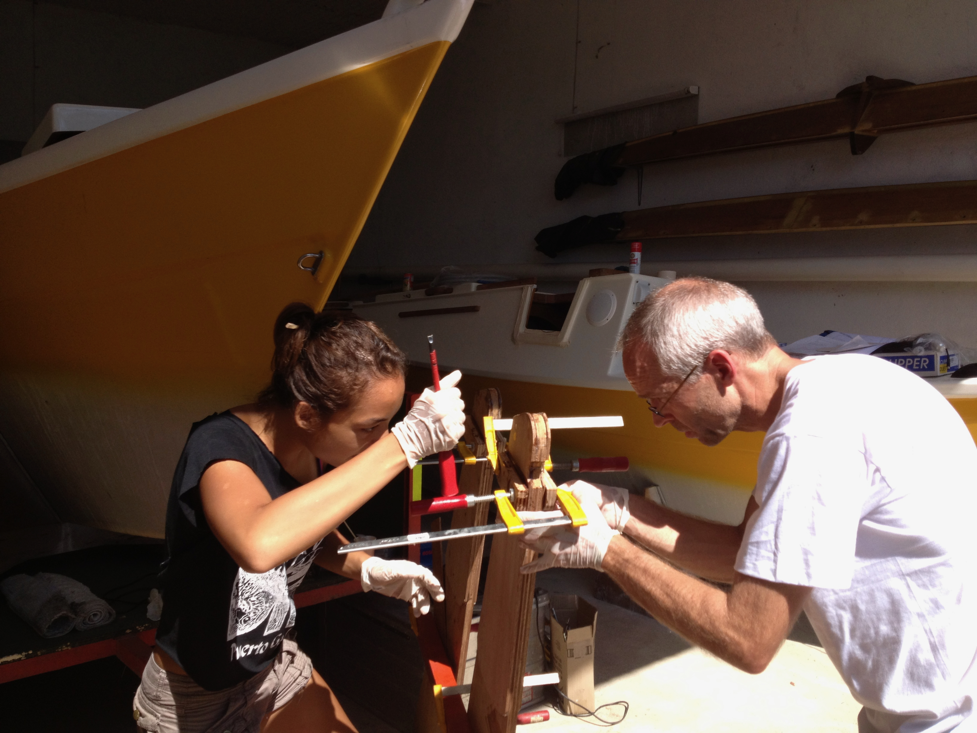
Help with Fitting the Rudders and Tillers
The tillers are quite long, so a small deviation in the angle they are attached with to the rudder will have a large effect in the cockpit. Some precision is needed.
The Rig
The Mast
The mast was made by Junction Boatyard from wood. It is hollow and coated with fiberglass. The photo shows the cross section of the mast and illustrates the types of wood profiles used to create the round shape, it looks a lot easier than the original Wharram design which involves a lot of sanding to get it in the round shape.
The mast turned out to be quite heavy, around at least two times heavier as specified in the construction manual. It worked a lot in particular during high waves so we replaced it later with an aluminium mast, but that is another story.
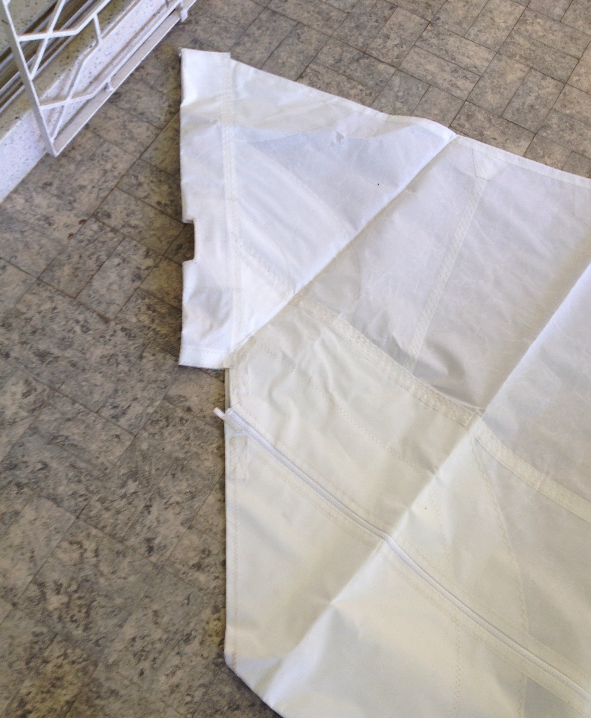
Sails
Amazing, Wharram sails are made by Hyde Sails in Cebu, a UK-Philippine joint venture. So it was easy to order them and have them shipped at minimal cost. Unfortunately the main sail came without the lashings on top to attache it to the gaff. So I had to return it to Hyde Sails and they fixed it under warranty. However, significant time and cost was involve din shipping the sails back to the manufacturer.
Navigation Equipment
Magayon will have some basic naviation equipment:
- Compass
- Log
- Depth sounder
- Chart Plotter
- Chart table
- UHF radio
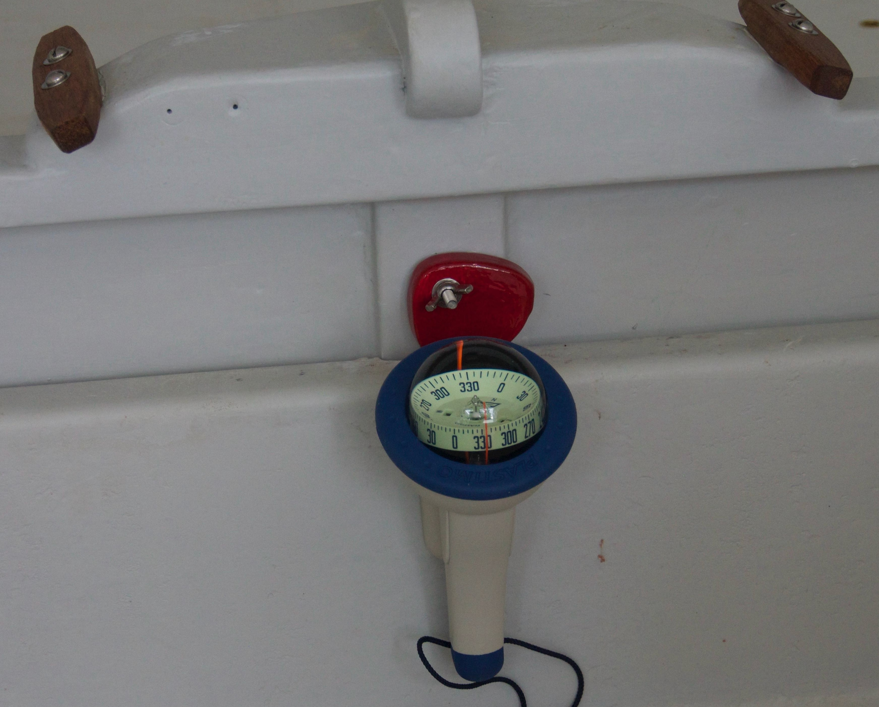
Compass
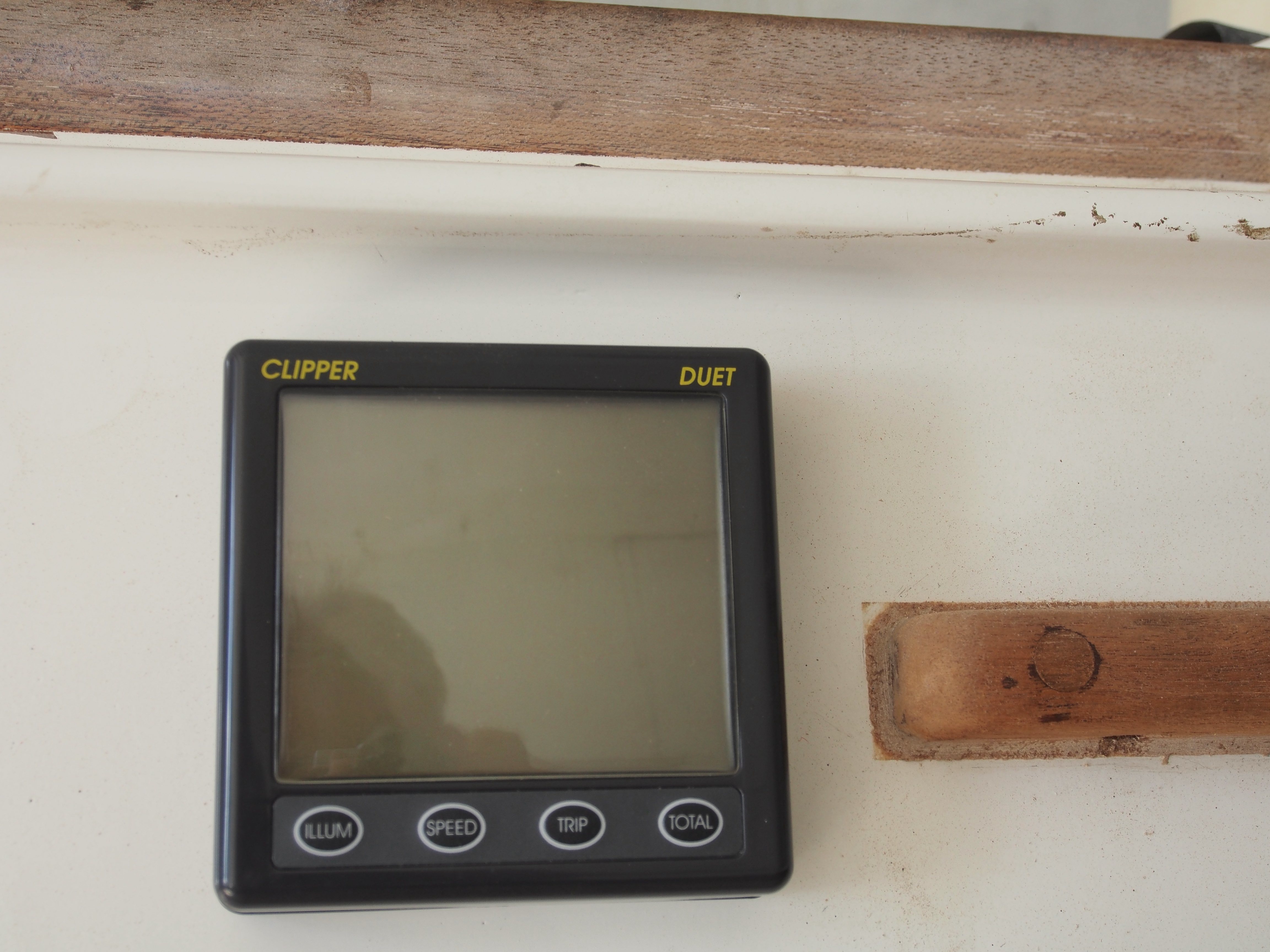
Log and Depth Sounder
For the depth sounder I had originally made an attachement that would be located on one hull and ensured that the sensor surface is horizontally oriented. However, this attachement turned out to be quite bulky due to the steep angle of the hull side walls and I was worried that it provides some serious resistance and reduce speed. The draft of the Tiki is very shallow, and because it is a catamaran it is not so critical if it touches ground. One would only need the depth sensor when looking for an anchoring ground, so it could be manually put in the water when needed.
cockpit side
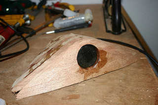
(idea abandoned)
The depth sounder / log compartment is in the port hull next to the radio. The depth sounder calbe can be attached after opening the comparetment and then be placed in the water e.g. attached to the boat hook with a shock cord..
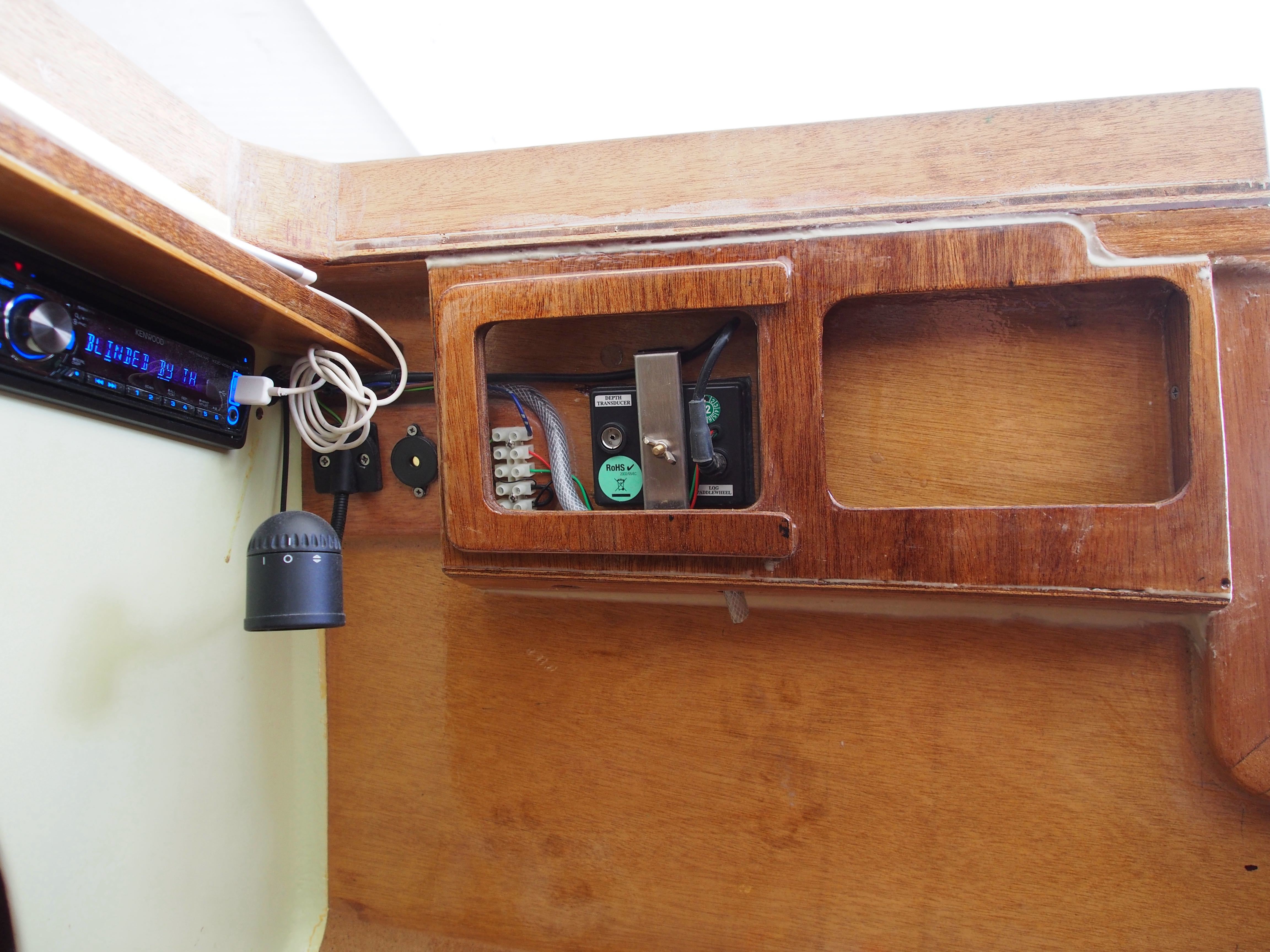
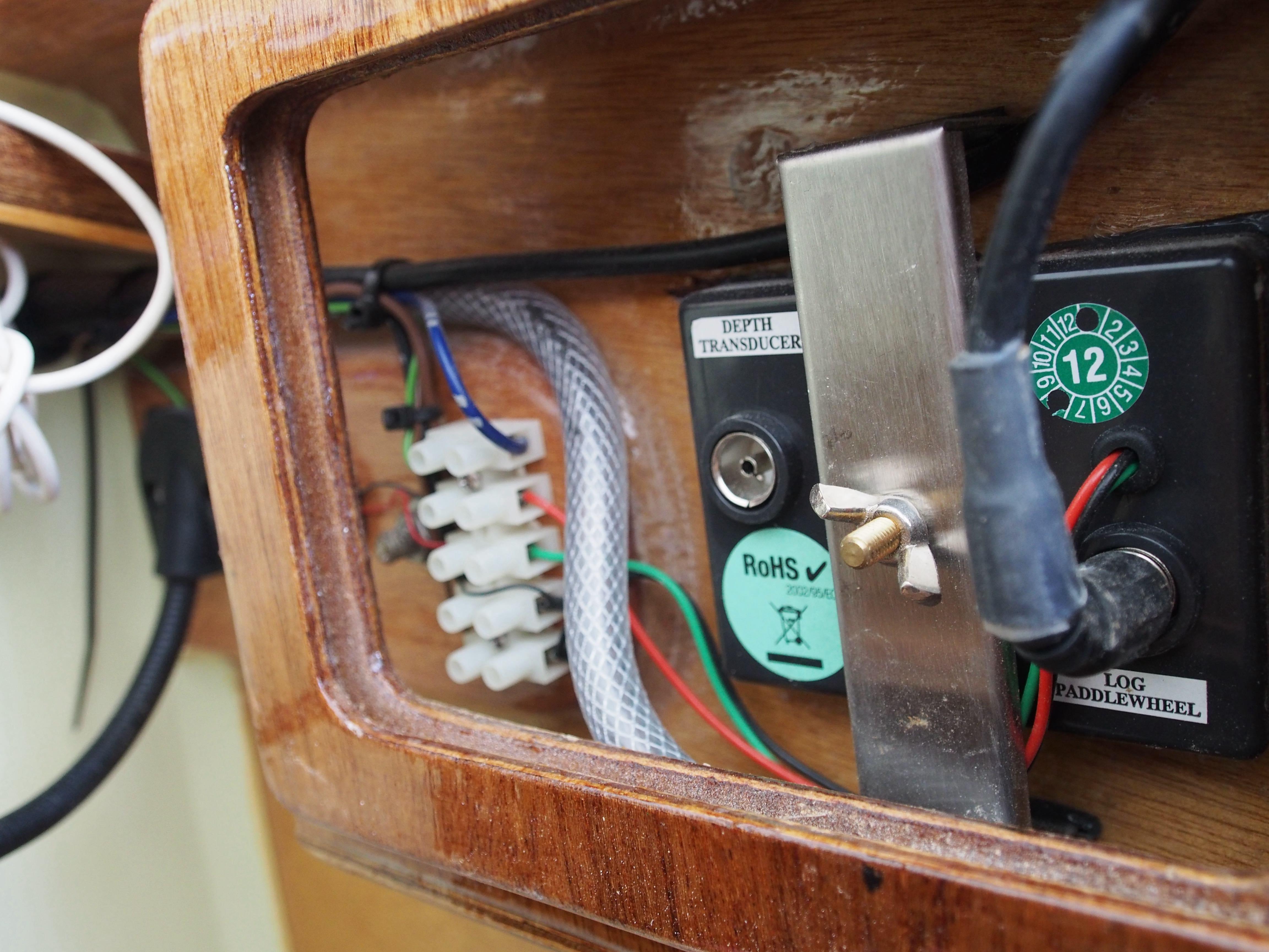
Chart plotter and Radio
An Ipad will serve as a chart plotter. The Charts for the Philippines cost less than US$ 50 and Ipads are in use by the family so this is the most cost effective solution. We also bougth a handheld radio for safety purposes, even if in some cases in the Philippines UHF radio was less effective than mobile phones for calling for help.
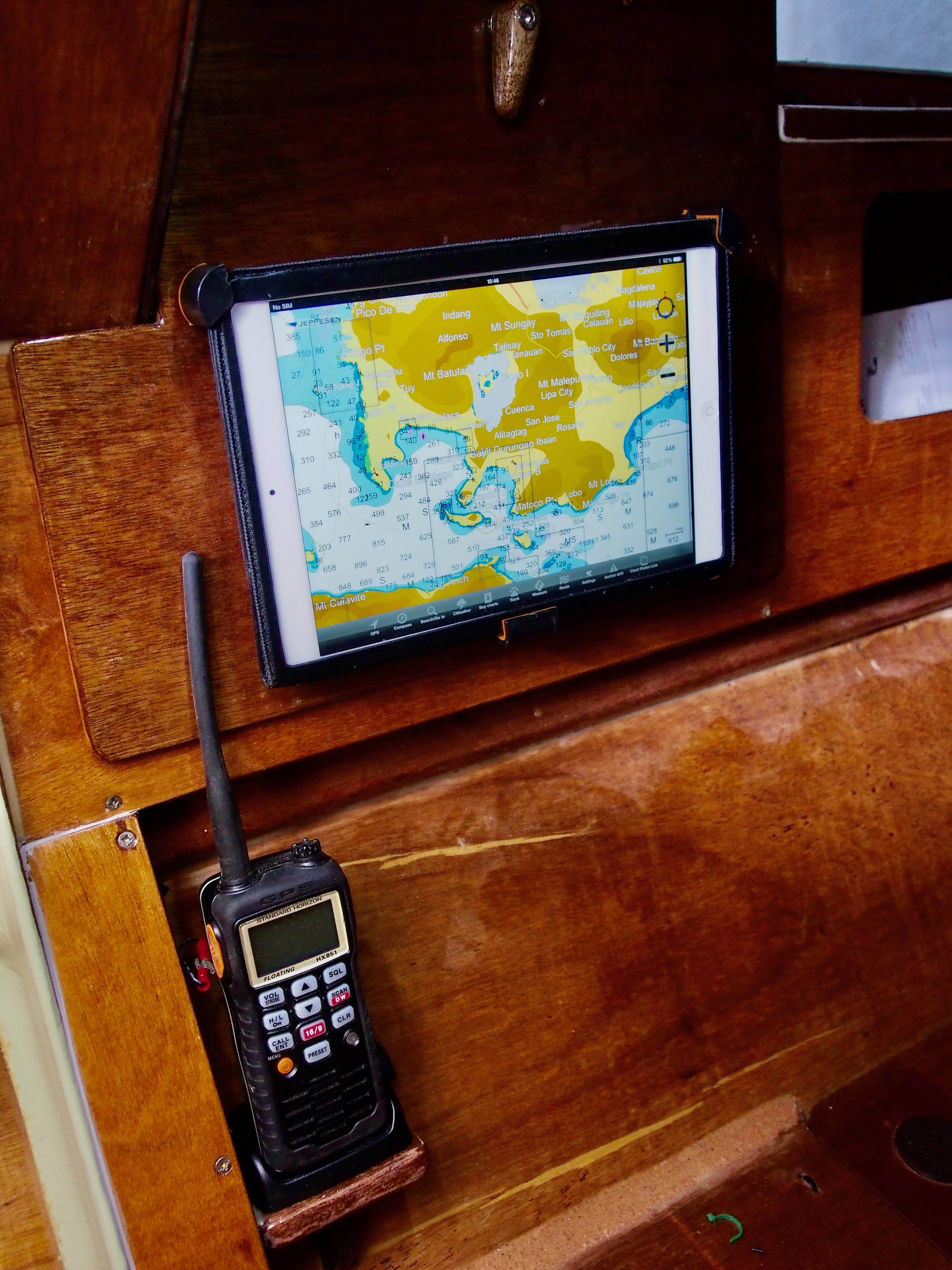
Chart Table
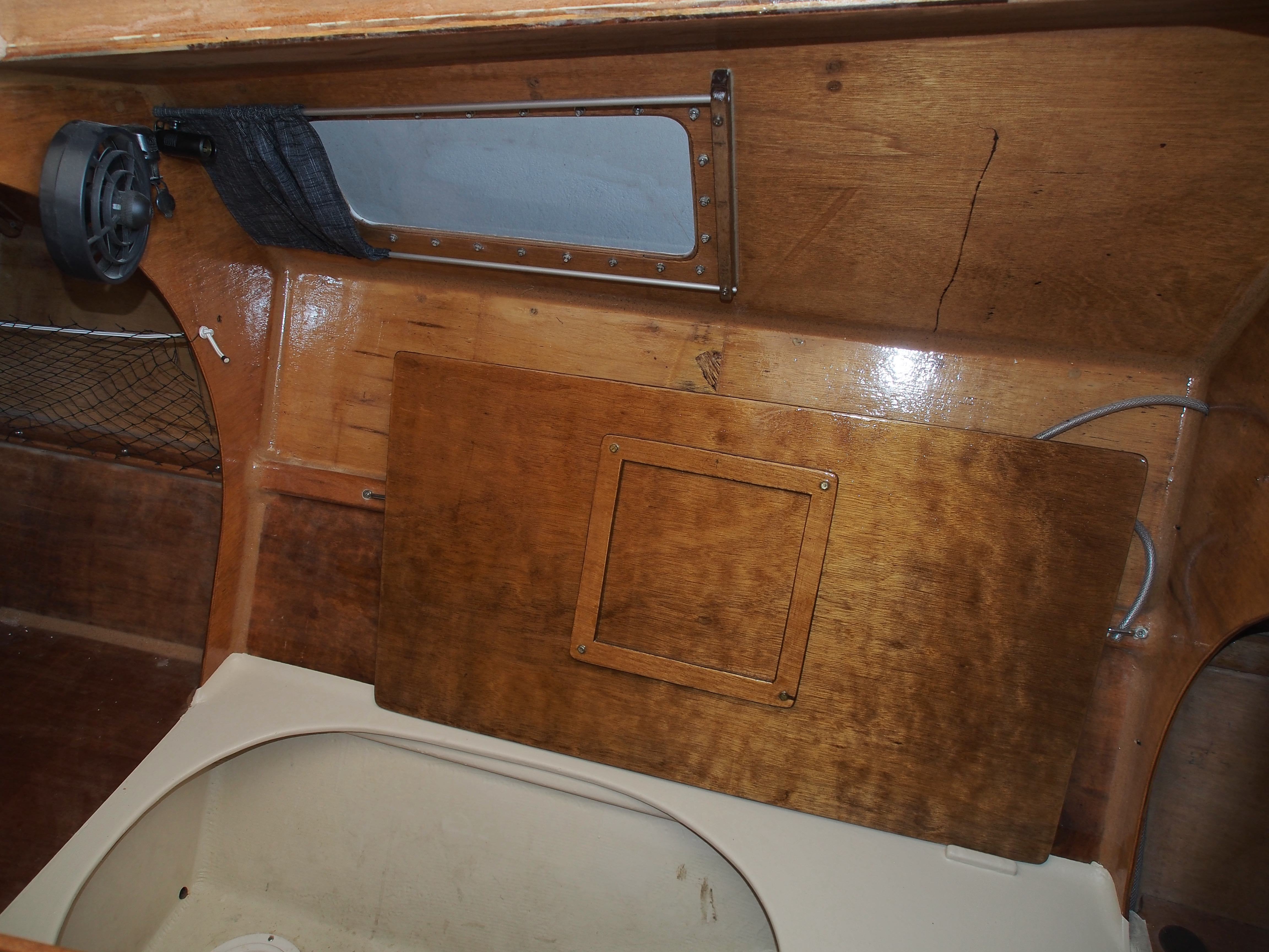
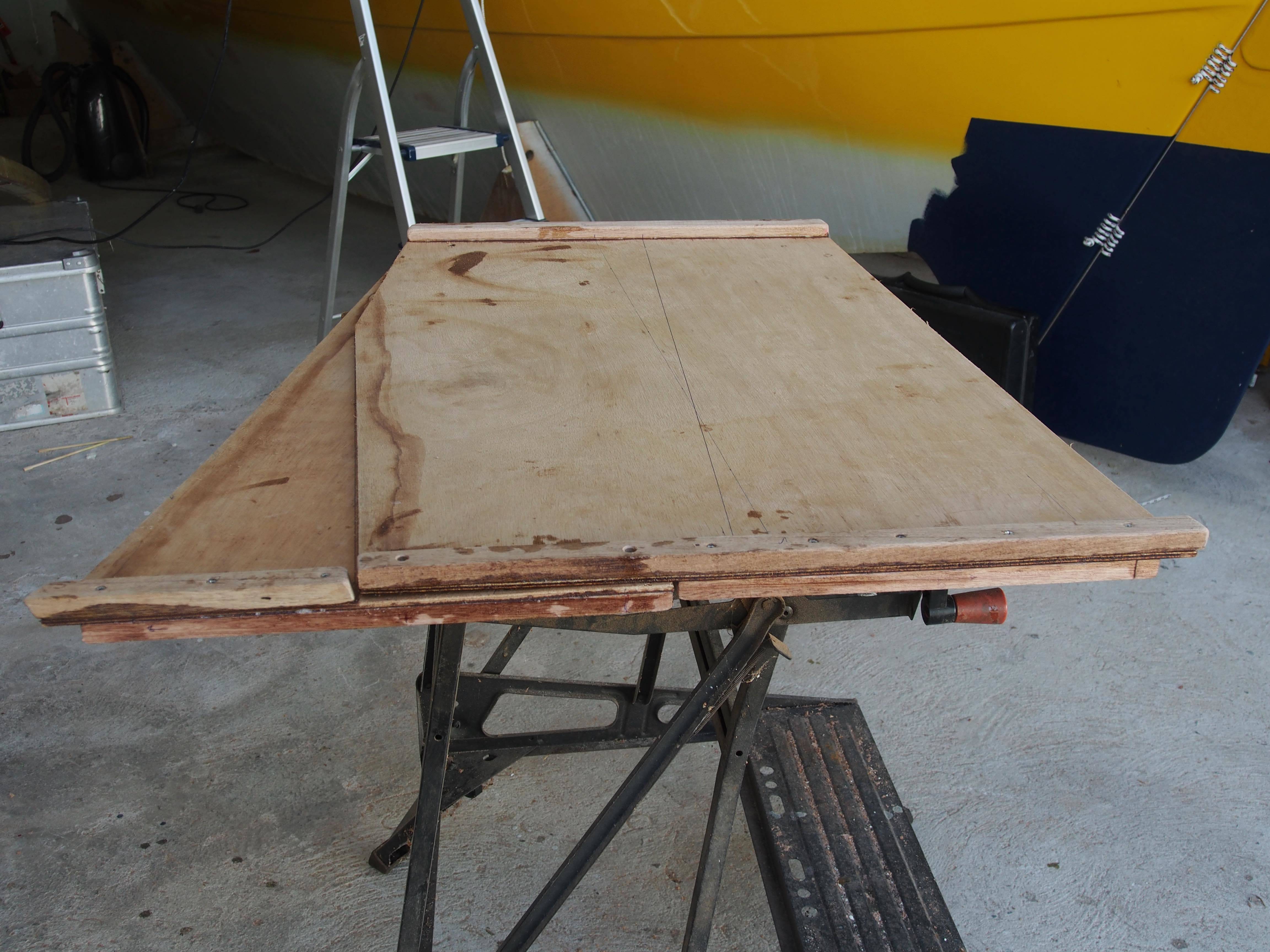
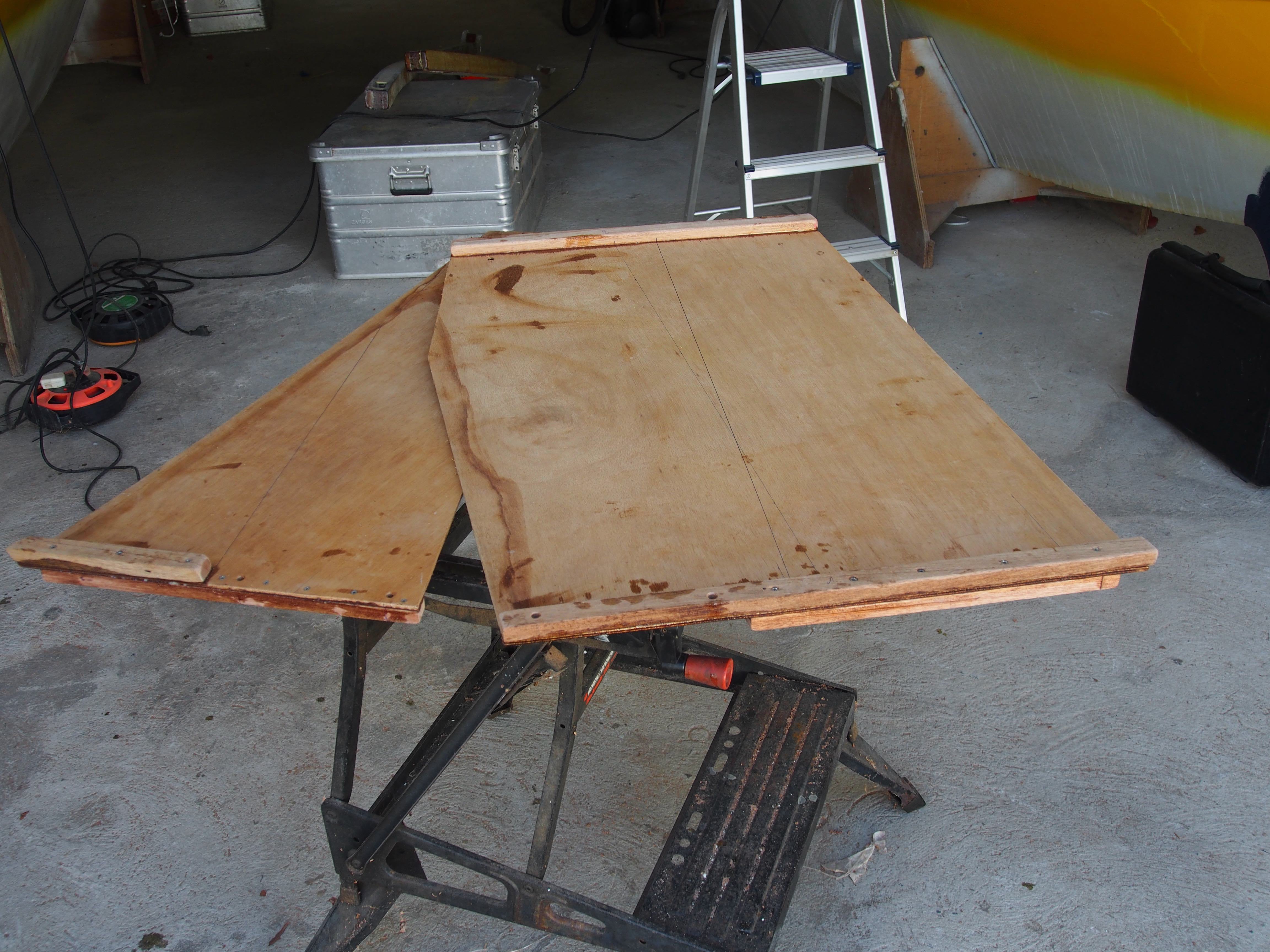
Both hulls have multi purpose tables. They can be eiter used as tables, as cover for teh foothole in the cabins for having a second bed, or stored away on the side as shown in the picture below.
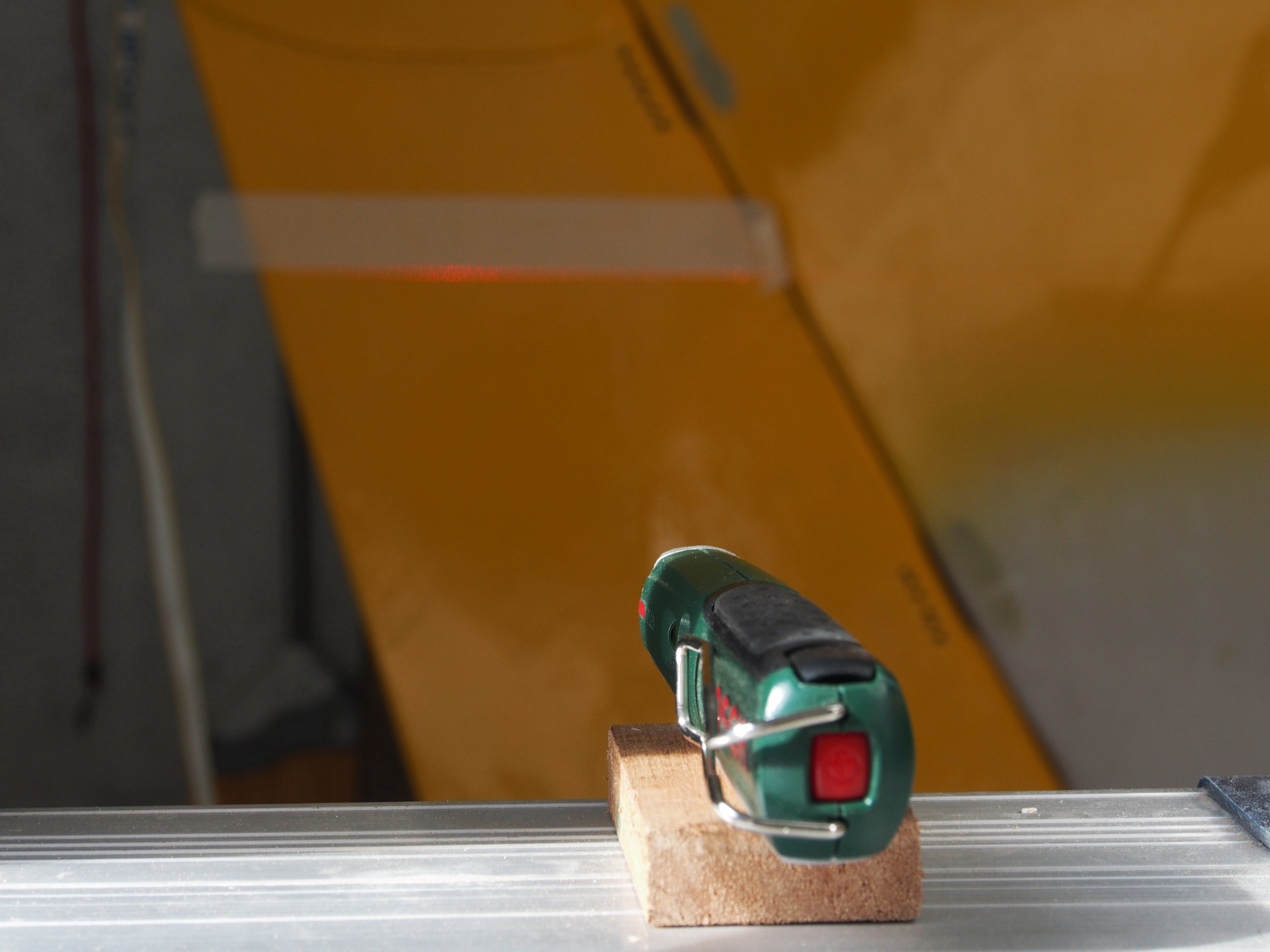
Assembly
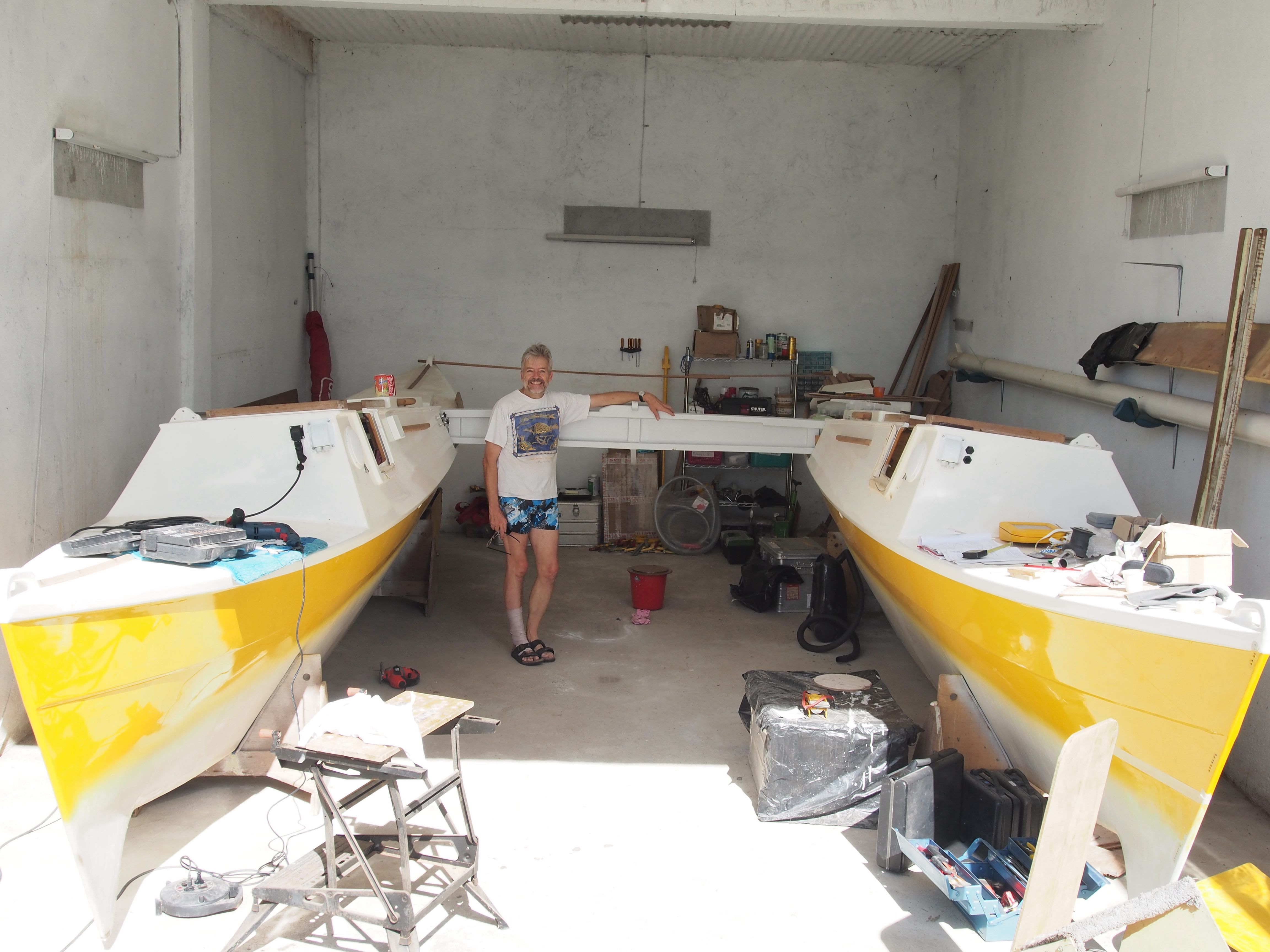
2014 is the year of the boat. After the many delays this year she MUST sail. It will be a very serious loss of face if Martin goes to Pandan Island for Christmas with anything else than Magayon.
January 25-29, 2014: So finally we got the port hull off the trailer and aligned the hulls using some sophisticated Bosch laser leveling tool. We also cleared up the garage for assembly. From now on progress should be fast. The trailer went back to Los Banos and is now parked in our garden, ruining the grass. We need a better solution for that. Walter recommended Ludring, his carpenter, for making the fittings for crossbeam locating blocks. And he is actually really good with woodwork. So finally we have a good carpenter to help.
Making the locating blocks for the center cross beam
Measuring out the locating blocks is a tedious job and it took me a while to figure out how to do it accurately. Each block has to be custom made. Because I only ordered the hulls and not the cross beams from Junction Boatyard the locating blocks were also still missing at the hulls. For the locating blocks we bought some Yakal wood, a hardwood that is used for the keel of Bangkas since it can be submerged in water without rotting. Junction Boatyard had provided the wood for the latching pads but it still needed to be worked in shape.
Fitting the parts for the locating blocks and the lashing pads.
February 8-9, 2014: One more trip with the trailer to bring the cockpit and a few other parts from Los Banos to Talisay. Not much work on the boat because Gerald and Lanke joined and we did a trip to crater island, the first since 1996. We left at 6:00 in the morning and had a fantastic boat ride with photogenic early morning lighting. Later in the morning four propeller airplanes, maybe from Lipa City airport, were flying formation maneuvers over Lake Taal. Leading to thoughts about WW2 air battles with Japanese Zero fighters in the sky above the Philippine and Corregidor.

March 2, 2014: Matthias was visiting the Philippines again and came sailing to Lake Taal. He had a look at Magayon and got quite excited, he happily offered to be crew next time he comes. He also acknowledged that the music came from the cockpit speakers and not from a “get to blaster”, and said he was impressed. Fitted the latching pads for the center crossbeam and designed and fitted counter boards inside. Glued them in place with help of Mavic.
March 8-9, 2014: Finished the locating Blocks for the center cross beam and the stopping pads on the crossbeam itself and attached the clamps at both ends of the beam. Removed the latching pads and sealed the holes and the counter boards inside. Then re-attached the latching pads and tied done the cross beam for the first time. Looks good.
The next step was to fit the cockpit. The big question: will it all fit together?
Kata and Mavic and a set of ropes to secure the cockpit in several intermediate positions helped to lift the cockpit in place and temporarily hold it using the aft cross beam. Looked good, all parts seem to be of the right dimension. I then made a frame that supports the cockpit in the back and holds it at the right height so that working on the aft crossbeam locating blocks could be done without the danger of the cockpit falling down.


Cockpit in place (left); Kata doing the first “Stress Test” of the cockpit (right).

Using the bow crossbeam to secure the cockpit while working on it (left);
The next step was to center the cockpit and cut the notch in the center for the strip in the center of the cross bean. For this I had to take the cockpit off the center crossbeam again, to hold it at the right height I used the bow cross beam placed across the cabins and some lace which secured it sufficiently to work on it with power tools.
January-March: I am getting an increasing number of Visitors every time when I am working on the boart. On March 2 Ritch was the first visitor who recognized what we are building: “That’s a Wharram, ” he said, “from down there it looked like a Sharpie…” He turned out to be from the Philippine Boatbuilder Group and gave me some tips about events, plywood and epoxy.
Status as of March 9, 2014

Figure above: Center crossbeam attached, aft cross beam temporarily placed and cockpit held in place and supported by a frame underneath. Front crossbeam is just placed loosely to get an impression.
A working holiday, Easter 2014
The Year of the Boat. And yes, we are going to sail to Pandan Island this year!!!
Yes, Martin decided to take shortcuts and use the techniques used by local traditional boat builders to safe time so that this year we can actually make it to Pandan.


Outrigger attachment in Lombok (left); Connection between engine and propeller shaft in Myanmar (center); Throttle control with fishing line (right)
“Joke lang”. We, Martin, Mavic and Kata, spent the Easter week at Walter’s to do some serious work on Magayon 2. Originally Miriam wanted to join too and help but she was busy directing her own film in Cebu, so we were missing her always enthusiastic help.
Here is a list of accomplishments of 8 days of work with several shopping and dining trip interruptions:
- Port rudder mounted (starboard rudder was already attached).
- Tillers fitted and raw tiller connecting rod made.
- Mavic made the curtains and the cover for the bilge pump hoses.
- All crossbeam locating blocks and lashing pads fitted and mounted. This took an awful lot of time. Despite me ordering the hulls from Junction Boatyard “according to the plans” they did not fit lashing pads and only provided the loose parts, most of them in raw form. They also did not fit the hulls with the reinforcement boards inside, which added a lot of additional work, and was a tough job, in particular for the bow cross beam where the inside could only be assessed through the small hole in the bow bulkhead. It basically took two and a half days for each crossbeam.
- Coated the starboard cabin floor with anti slip deck paint (port cabin was already done).
- Water proved the solar powered vents with Sikaflex.
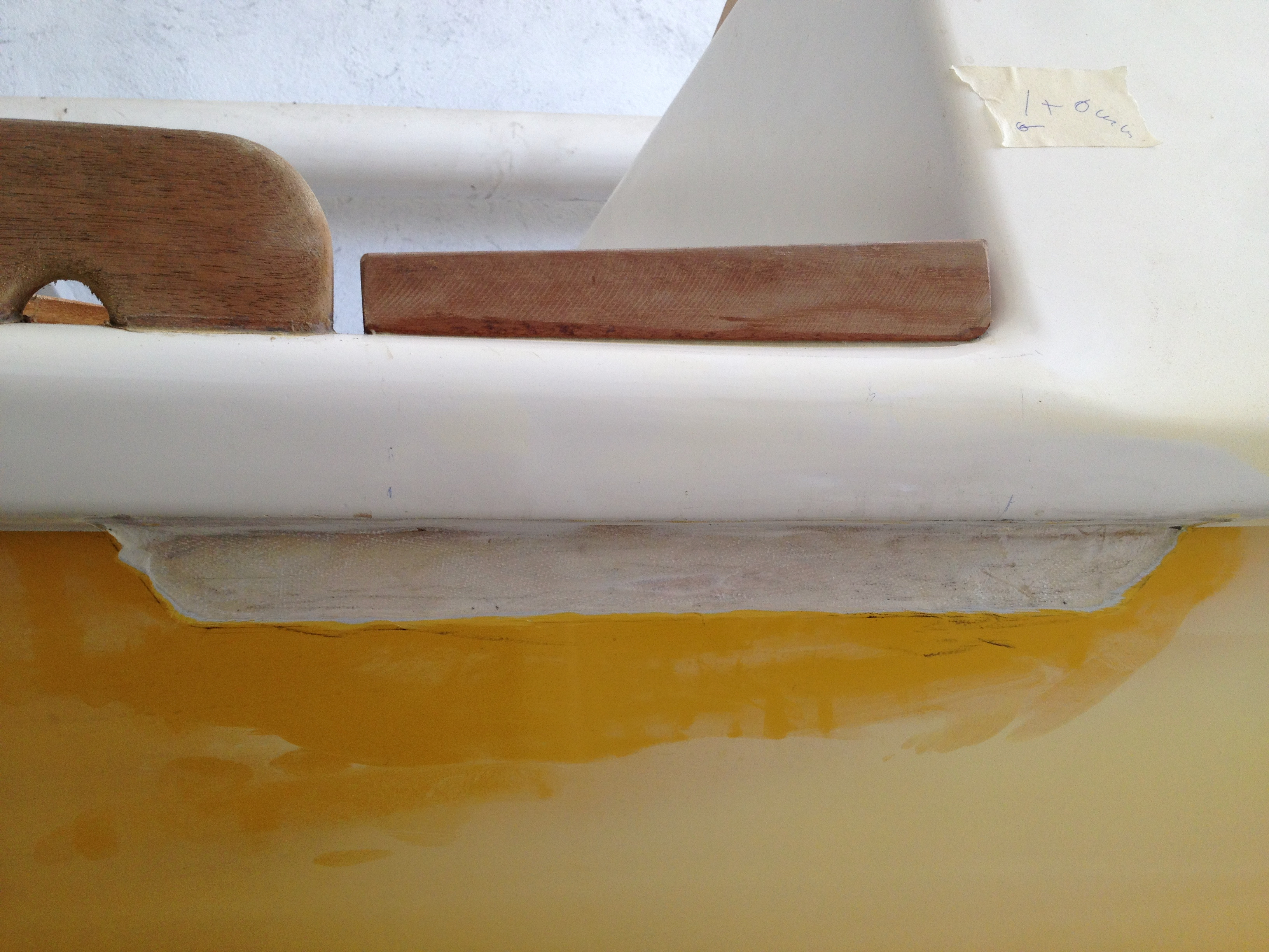
- Fitted blocks at the cross beams that prevent the cockpit from moving sideways.
- Fitted the canvas seat fastener bar plus the reinforcement bar inside the cabin (again, the latter should have been done by Junction Boatyard)
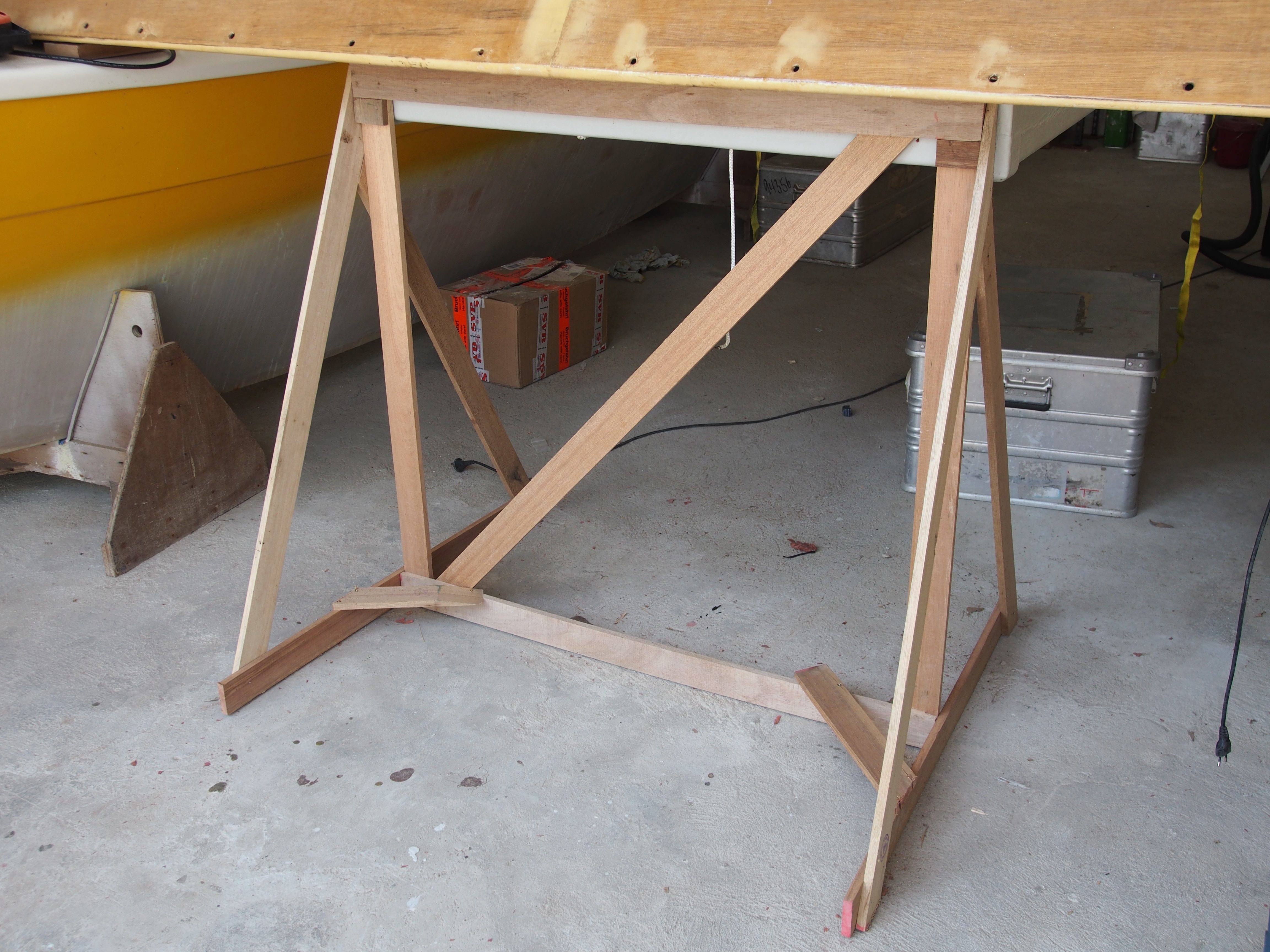
- Made and fitted the four bars at the sides of the cockpits that prevent the cockpit sides from bending towards the hulls.
- Fitted the second winch. For this we bought the most expensive screws ever, stainless, made in Ohio, sold by a hardware store in Talisay for 120 Pesos (US$ 3) each, excluding the nuts, which were another dollar each.
- Fitted luggage nettings in the port hull and in the center section of the starboard hull (the nets in the front section were fitted by Miriam before).
- Bought hardwood for the aft net fasteners, outboard motor bracket and tiller connecting rod. It is very difficult to buy proper hardwood in the Philippines. New wood is just not available. Some shops have “second hand” hardwood of which sections can be re-used. A result of uncontrolled deforestation.
- Made the cover for the starboard hull electrical connector board cabinet.
- Finished kitchen table / foot hole cover of the starboard hull.
- Started laying out the rig: Sheets, halyards….
- Ludring, the carpenter of Walter, started making the gaff and some other small parts that are still missing.
Cabin interiors – finished, finally.
Some pictures
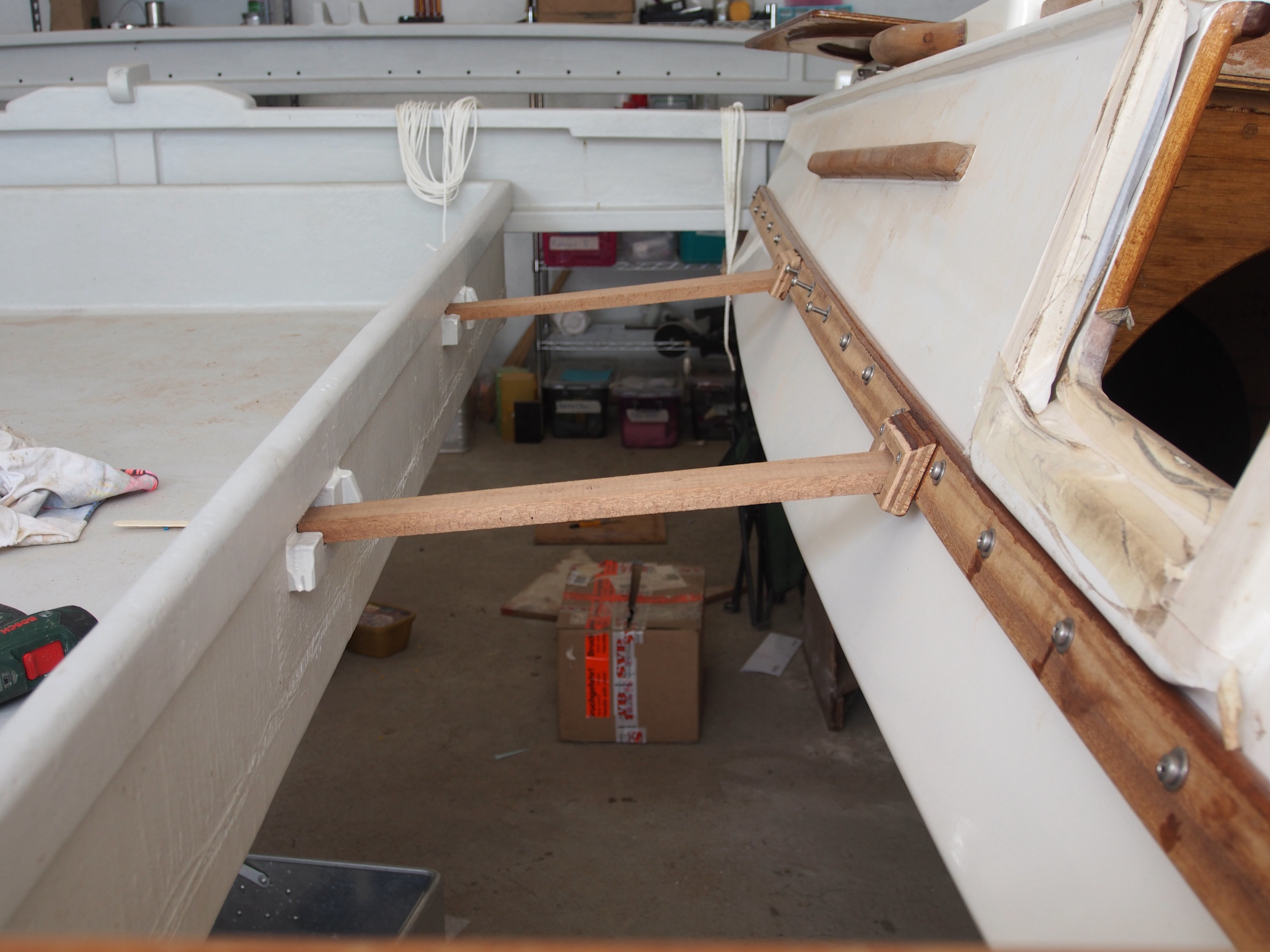
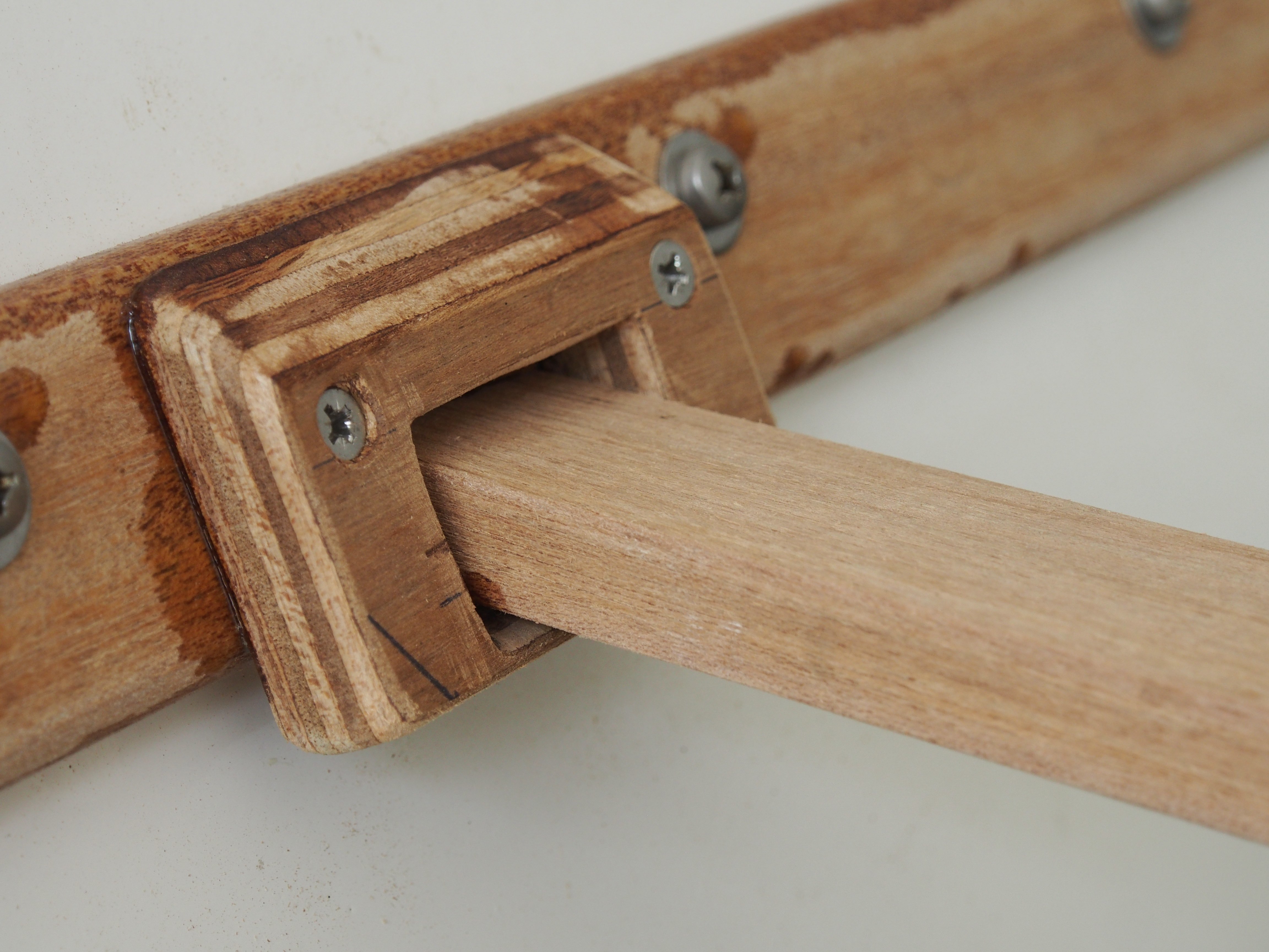
Figures above: Canvas seat fastener and bars that prevent cockpit side from bending


Figures above: Curtain closed (left) and open (rigth), kitchen table at the side of the cabin, it can be used to cover the foot hole to provide an additional sleeping area.


Figures above: Nettings for luggage in the starboard hull


Figures above: Locating blocks for for aft cross beam (top left), locating lock and lashing pad, still needing finish (top right); glueing in stopping blocks in crossbeam to lock the hulls sideways (bottom left); bow cross beam lying on fitted locating block (bottom left). The addition at the center of the bow crossbeam is for the anchor rope.

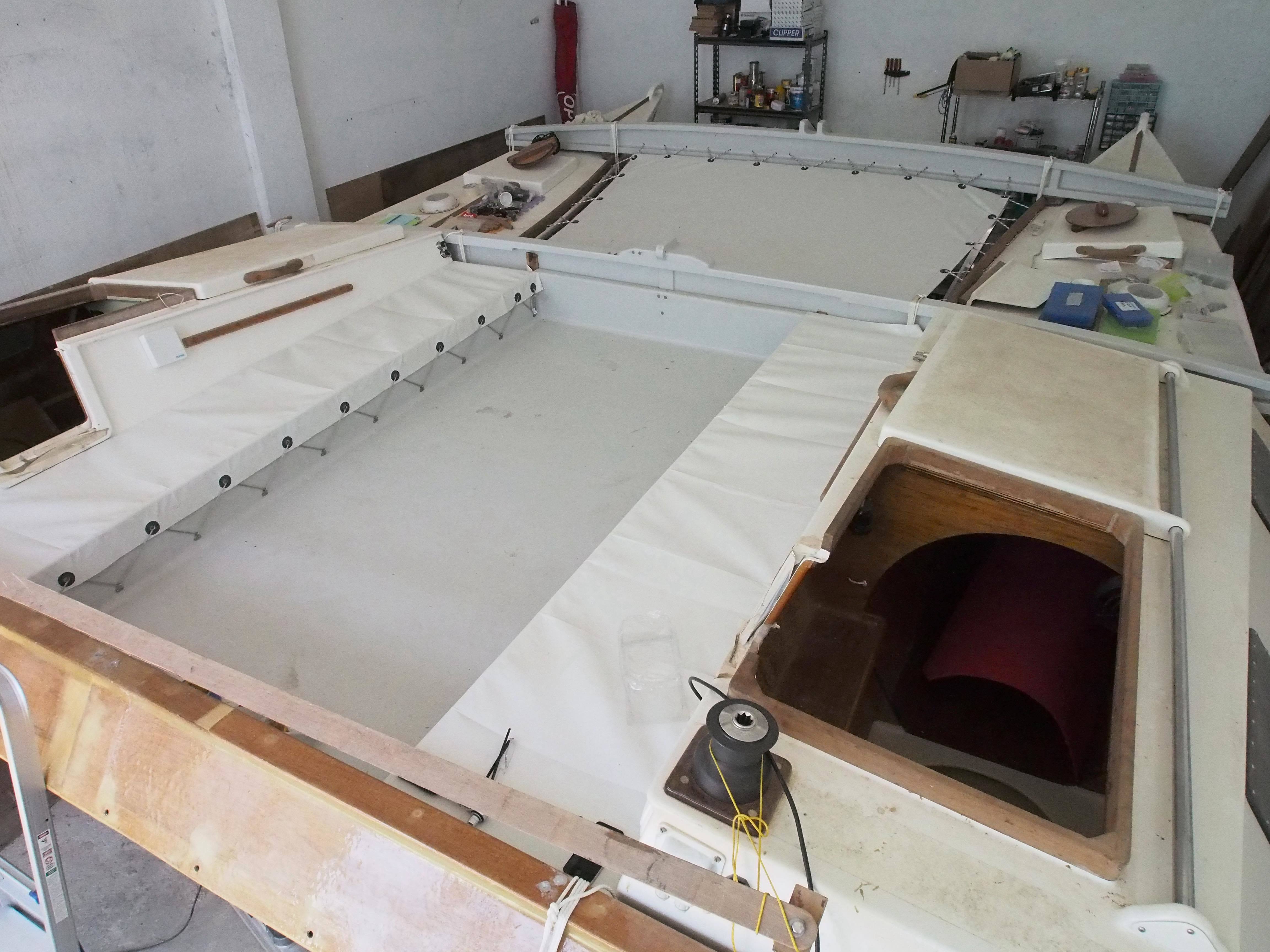
Figure above: Status as of April 20, 2014 – All crossbeams and cockpit mounted. Canvas seat fasteners fitted but removed again for final finish and waiting for the canvas seats. Trampoline is ordered.
It was extremely hot over Easter, approaching the hottest season in the Philippines. Drink consumption was half liter per hour.
Oh yes, before I forget mentioning it: The Wharram plans are amazing. You follow them and when you assemble the boat using all the different parts made, everything fits and is off specification only by millimeters.
Progress after Easter
17-18 May 2014
A very hot weekend with Kata, the reset of the family was busy. May is usually the hottest month in Laguna, productivity was consequently very low. I managed to desing and make the outboard motor bracket (using an 8hp Yamaha motor borrowed from Matty), and cut some wood for other purposes. And I finally managed to fix the broken wheel of the Opti trailer. The outboard bracket needs some more finish, maybe another hour and then only the gaff still needs to be built. All other parts are done. Consequently the moods were flying high on the way back.

Magayon as left on May 18.
23-24 May – Frustration
A disaster weekend. When I started working on the boat on Saturday the carpender came and brought back three parts we had agreed on him doing. One part was all right, the other two were made from the wrong wood (softwood instad of hardwood) and the third was completely screwed up. It was the tiller connection bar, I had spent half day preparing it, glewing different pices of wood together. They just needed trimming to the reight width. The carpender had left the width but cut the length rendering the part unusable. Frustration in its highest form, I spent half a day, gave clear instructions and then the whole preparatory work was just runined by two saw cuts at the wrong place.
Fed up with local help. Back to working alone.
7-8 June – Trampolines
Got the trampolin and the canvas seats I had ordered from GrainPro delivered and managed to pay Tess for it in Myanmar. When back from the trip the goods were already delivered, Mavic had bought some more milled fiberglass, so lots of work waiting to be done.
Mavic and Kata helped fitting the seats. Teamwork, me crawling underneath to fit the screws in the wooden bars that attach the canvas seats to the hulls, Kata inside the hull fitting the washers and nuts and Mavic checking on in the cockpit for even tightness of the canvass seats across the length, a pretty tough job at 40 degrees heat inside the boat shed. I also did some more work on the outboard bracket and re-built the tiller connection rod the carpender had ruined two weekends before.
Trampolin and Canvas Seats fitted, raw tiller connection rod provisionally mounted.
The mood was obviously a lot better than two weeks ago.
When arriving at home I put together the hopefully last order to SVB for little things that are still missing and two outboard motor tanks that fit the space in the cockpit.
June 21-22, lots of small things make a big one too
This weekend I went with no particular plan because from Saturday to Sunday night (3:00 – 5:00) Germany was playing Ghana in the Worldcup, an exciting game we watched in the German Club in Manila (2:2 draw). I assumed that I would not get a lot done on the boat this weekend. Nevertheless we made good progress:
- Rocks off: Finally connected the starboard hull electrically with the port hull. Main power plus audio. From now on stereo sound fills the boatshed when I work on it.
- Installed the charger and electrics for the UHF radio.
- Got stainless steel angles to mount the outboard bracket to the cockpit made and mounted them. Tested the bracket. Made epoxy fillets for all the screw connections.
- Designed a shelf for the aft cabin bit of the starboard hull for the kitchen wear. Since the cabin is much wider than the opening, and the shelf needs to be removable to assess the aft compartment and service the water tank hoses, the shelf needs to be collabsible so that it can be removed and taken out. I came up with one that consists of two parts which hinge around a pivot point.
- Fine tuned the tiller connection rod and re-inforced it at the contact points with fiberglass. Same with the tiller ends.
- Got a much better idea for a bathing ladder.

Attempt to make a shelf board for the aft cabin of the starboard hull. It needs to be foldable so that it fits through the manhole but also covers the whole width of the cabin. Looks promising.
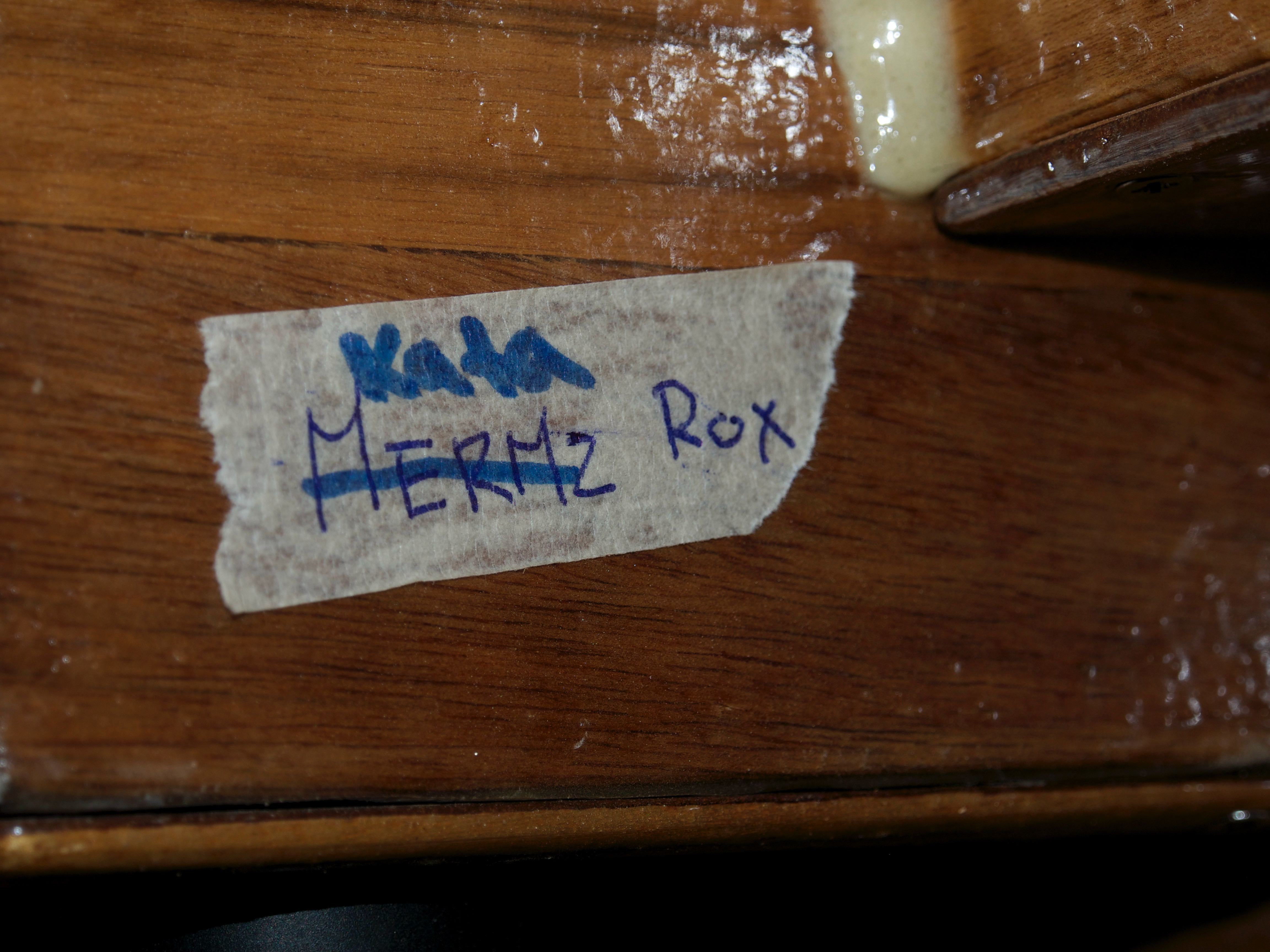
Secret messages like this one found all over the boat
Yesterday, December 6: The assembly is as good as completed
We finished the major bulk of work and assembled the boat except for the rig on Friday, December 5. To be able to launch before Christmas we decided to to the final paintjob on the cross beams and the cockpit in 2016. So these parts are just covered with primer, but they look actually OK.
We wanted to launch this weekend but the approaching super typhoon Hagupit sort of spoilt the mood, you don’t want to be out on the lake the first time with a new boat that still might have problmes with a major storm arriving. So we will launch next weekend.

Above: Coating the port bow hatch with rubber as protection from the heavy anchor and chain, a very invonvenient job, postponed to the last minute.


Mattresses made from closed cell foam so that they could be used as floats in case of emmergency. Thicker than a camping mattress, but obviosuly not as compfortable as the bed at home. Left: the main berth ; Right: emmergency berth.


I borrowed Matty’s 8hp longshaft outboard motor (rigth). Two gasoline tanks strapped into the cockpit (left). Bathing ladder made from a household aluminium ladder, we will see how sea water resistant the stuff is (right). The tiller system in red with a tiller extension.


Left: The trampolin, Miriam already claimed it as her sleeping quarter. Removable compass below the mast foot on the center cross beam. The hatches and the cabins have one solar powered ventilator each for removing damp air. Right: Mavic removing century old masking tapes that were used to protect the paint while working on the hulls.

Assembly completed
To prepare the launch next weekend the carts with the wheels were put under the hull and balanced with around 20 kg excess weight on the bow. For four people it should be easy to roll the boat down to the ramp and in the water.
Hier
