This needs a full rebuild, but that’s actually a good thing…
What happened?
Well, after all, the boat is 40 years old. One could say, without exaggeration, that the electrical system is a bit outdated. In addition the boat was recently hit by a lightning, according to the previous owner it fried the whole electrical system. The caretaker said that when he turned on the electrics after the lightning struck, there was smoke coming out of the switchboard. So they did not use it anymore but installed some basic items like cabin lights in a parallel system. When we inspected the boat, all instruments had been taken out for varnishing the wooden panels they were mounted in.
And what is worse, rainwater is leaking into the electrical compartment through the starboard traveller. It has lots of cracks and needs urgent repair.
The situation looks grim, but it is actually not too bad. It prevents me from trying to do quick fixes and encourages me to redo the electrics from scratch. This will be my fourth electrical boat systems, after those of Magayon, Sancara, and Magayon II.
Design principles
There are a few design principles I will stick to:
- As little automation as possible.
- To keep the carbon footprint low, use as much as possible re-cycled materials, except for the key electrical components like fuses, switches etc. See also the ideas behind the Ellen MacArthur Foundation (EMF), which promotes the idea of a circular economy.
- Scrap legacy devices and use state of the art technology (e.g. LED lights, USB C outlets…)
- Use of the open source OpenPlotter for the new brain of the boat.
A phased project
Since we want to do sailing and not just repairing, we will implement this in three phases:
- Phase 1: Restoring basic functions needed for shorter cruises and to be legal.
- Phase 2: Adding some comfort functions (e.g. a chart plotter…)
- Phase 3: Using the boat as a platform to experiment with all sorts of new things.
Batteries
There are three batteries, one for the motor and two house batteries connected parallel. Unfortunately the house batteries are maintenance free automotive car starter batteries, not deep cycle batteries, so not really suitable for the intended use. They will work but will have significantly shorter life compared to true deep-cycle batteries.
“Motolite Enduro 3SMF / N70 Maintenance Free Car Battery.” One of the two has been replaced recently. There is no information about the capacity.
Automotive starter batteries are designed for delivering high cranking current for a few seconds, to stay mostly fully charged, and to provide shallow discharge only. They are not designed for deep regular discharges (50-80% discharge), long, slow drains from lights, instruments, autopilots, fridges etc, and repeated cycling common on sailboats. They are acceptable if: Your house loads are light, you mostly run the engine frequently, rarely discharge below 80-90%, and if I am OK with shortened battery life (which I am not). Under typical cruising sailboat conditions starter batteries last 6-18 months compared to 3-7 years for deep cycle batteries and 8-15 years for LiIon batteries.
One really annoying fact with Motolite batteries is also that there is no data on capacity (in Ah). The Motorlite web site does not have any information on capacity. A search in the internet resulted in the range of 60-75 Ah. Really annoying. How can you design an electric system if you don’t have that very basic data? It’s more fun in the Philippines.

The Control Panel
The Control Panel as the center of the electrical systems. The old one (Picture) is totally gone and will be ripped out and replaced with a completely new design.It does not close anymore, so it is held half close with a cable.
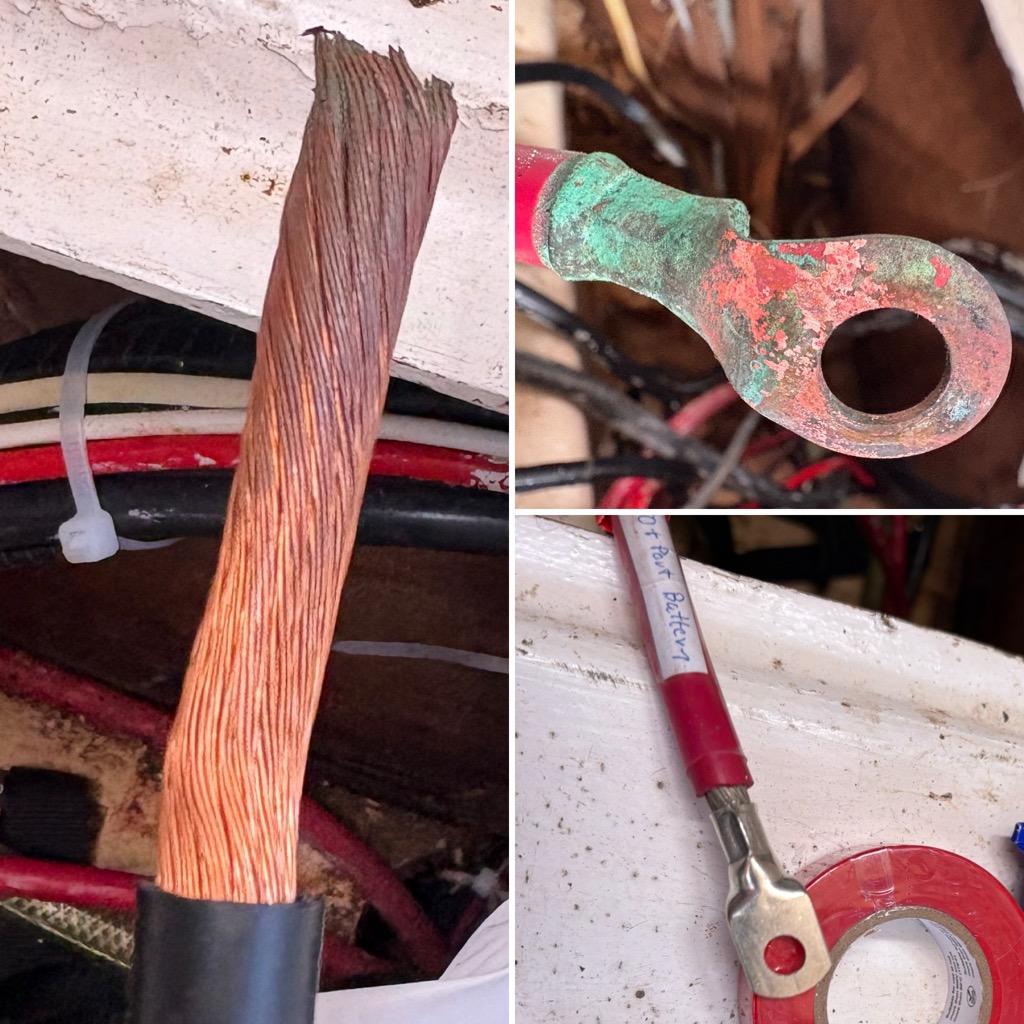
40 year old cables
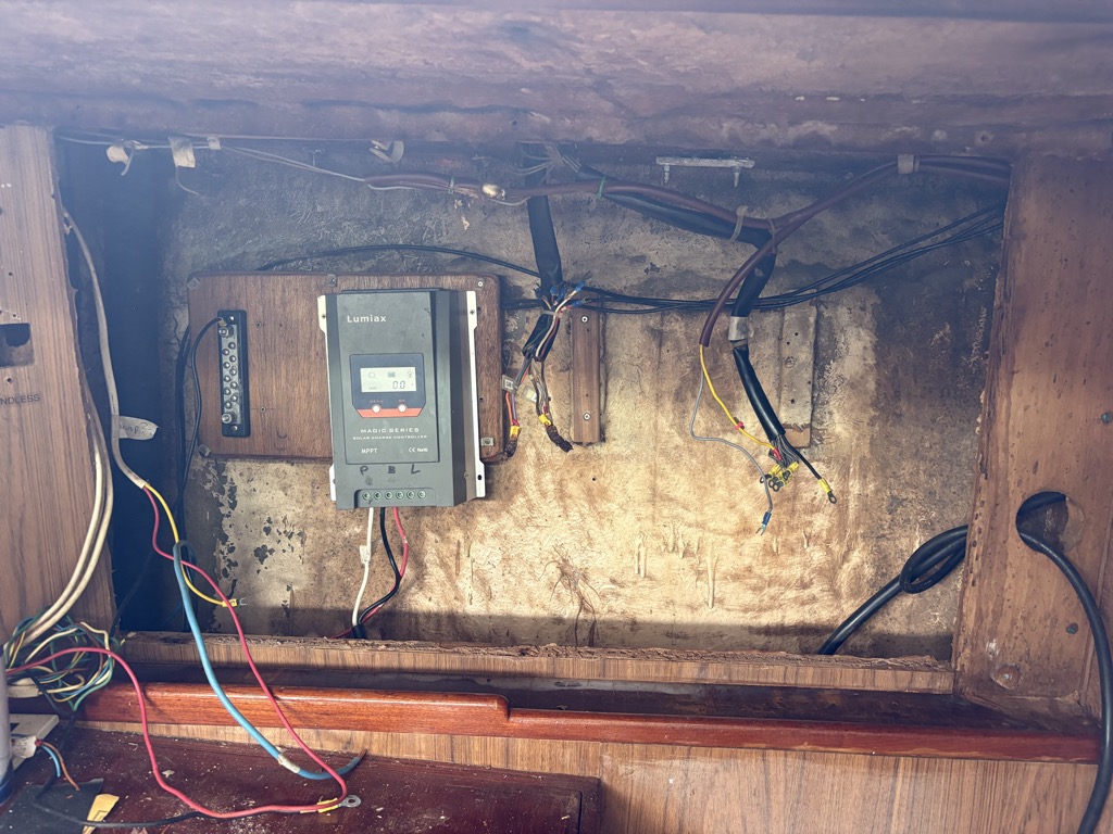
The boat, and its electrics, is 40 years old. Things have been added, obviously often not following best practice. Added wires are not tin plated and some are solid core, a no-go on boats because they can break when exposed to vibrations. When I touched some connections, like of the wires running from the battery to the solar charger, the crimp connectors just broke off. Most of the contacts of the switch panels are corroded.
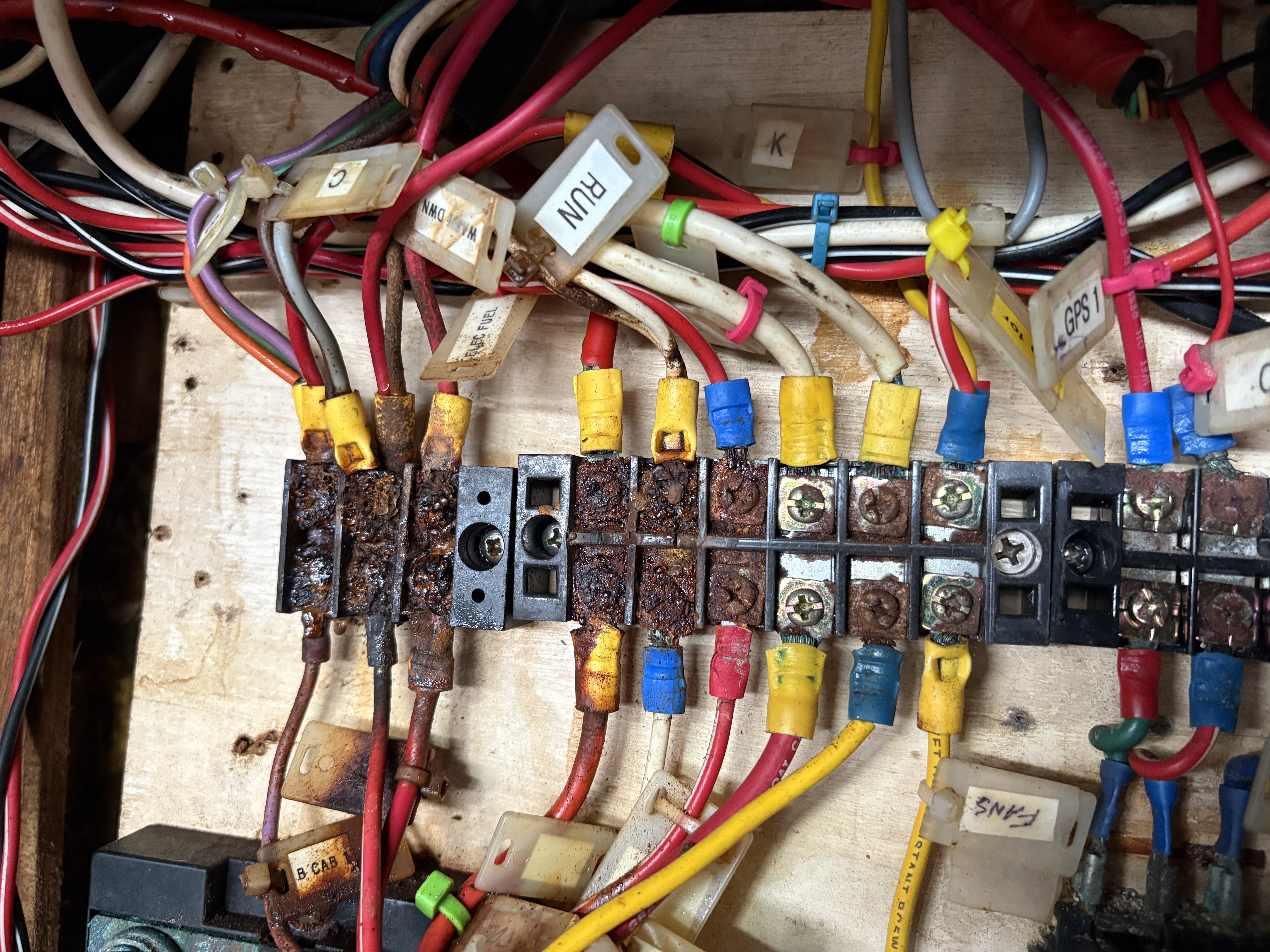
The board that contains the terminal strips looks even worse. Also see all the free hanging wires, from stuff that was added during the lifetime of the boat. At some point the boat had a generator and an aircon, therefore there were many components of a 220V (or 110?) system of some sort. The thick black and blue cables for example in the picture were from that added components.
A bit of detail: terminal boards, totally corroded. These look like some cheap Chinese parts. Interestingly, the ground termin bar on the top right in the picture above is not corroded. Probably a good quality with corrosion resistant metal from the original set-up.
What did not help much is rain water dripping into this compartment through the foresail traveller mounts. That is the first thing that needs to be fixed.
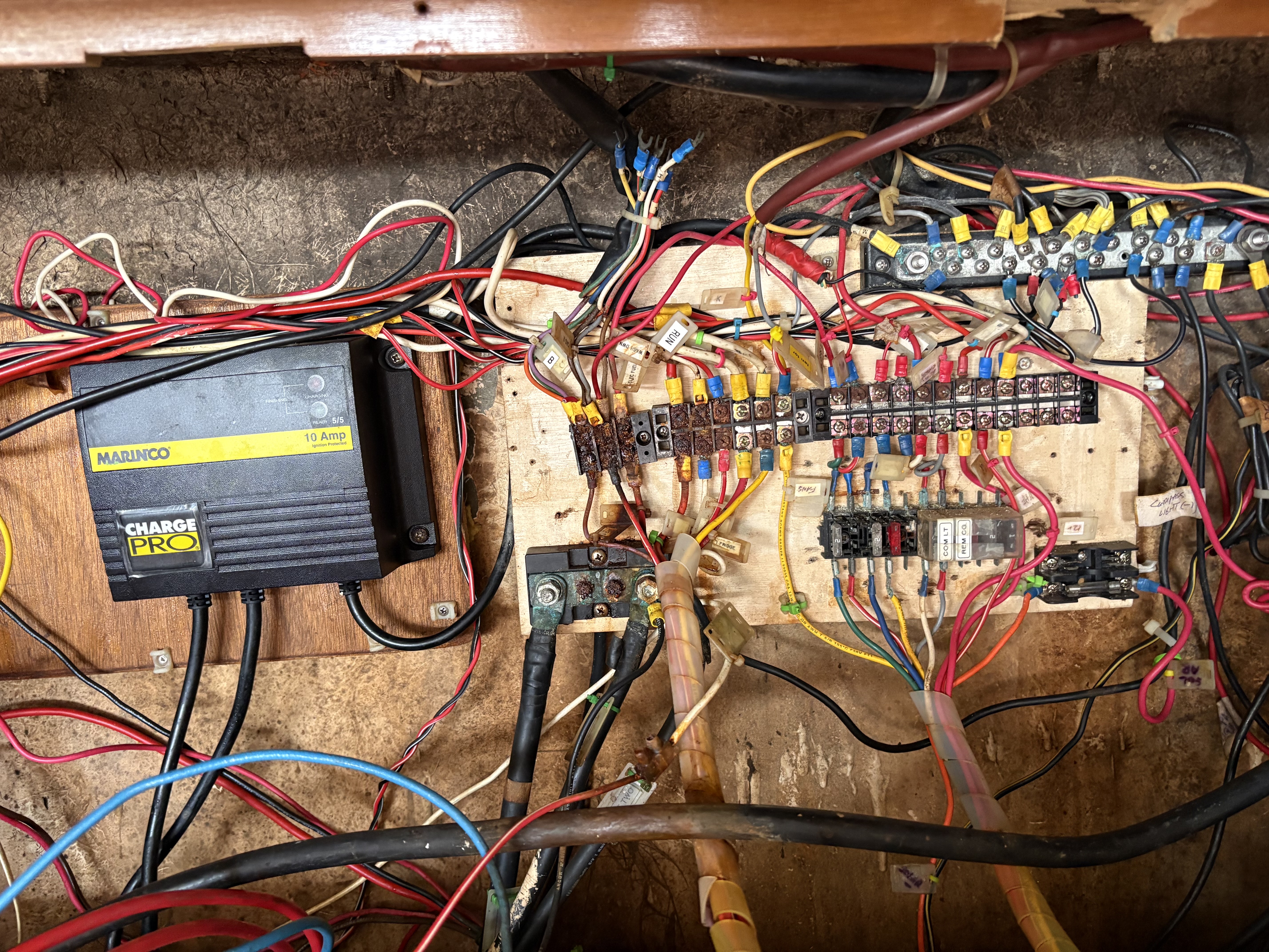
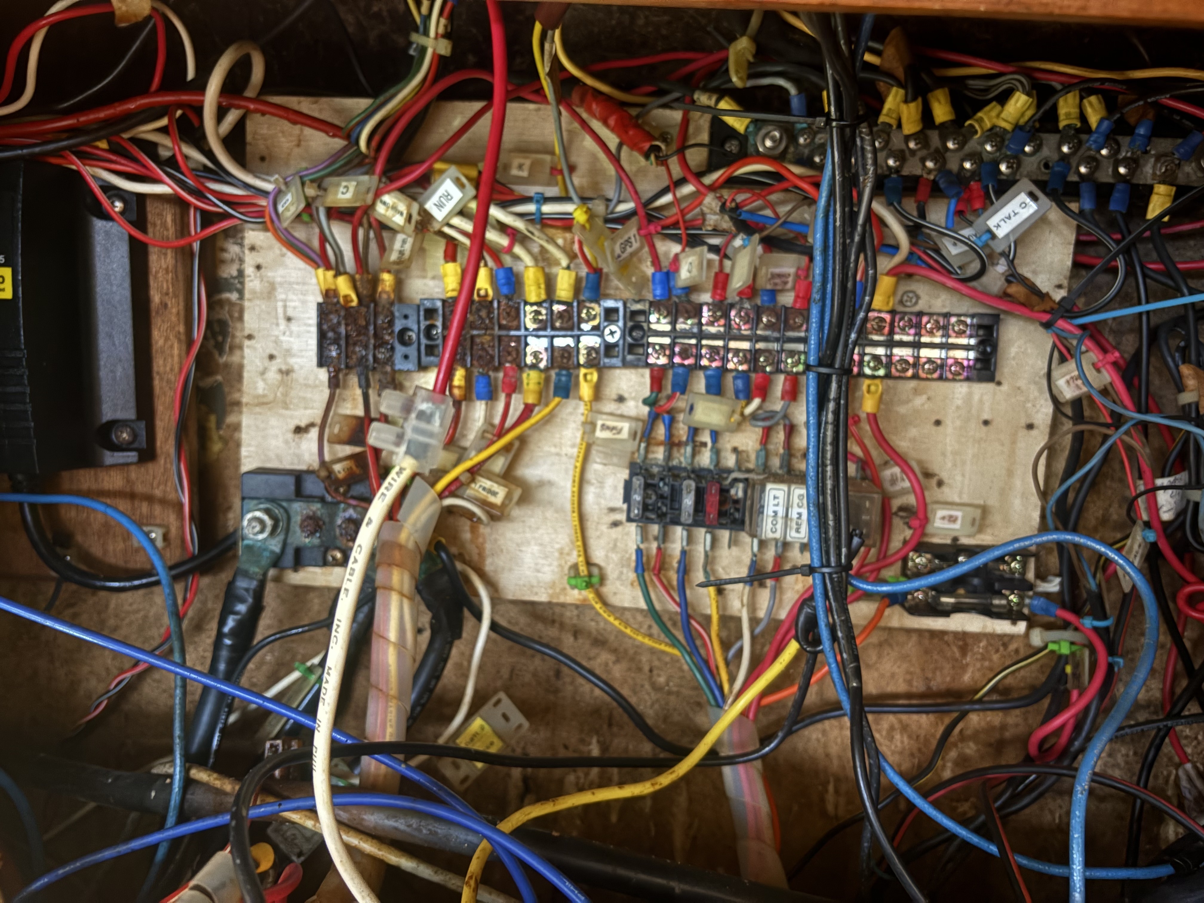
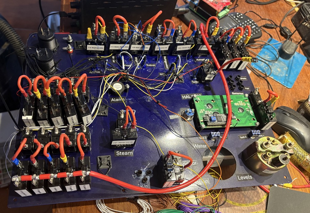
After taking all added wires out and removing broken or unused components this is what is left. Still quite a lot of added stuff, but the next step is now to remove the remaining connections and label the wires (the masking tape on board was soaked and not useable for that anymore), test them for resistance and insulation and deciding whether they can still be used or need to be replaced.
A new rail terminal board needs to be made
I stopped here, because I now have a good idea what needs to be done, and what can be kept. Right now the priority is to fix the leaks in the deck where the travelers are. As long as water drips into the cabin and in particular in this compartment, any work on improvements is useless.
Update: October 28: After two more trips and trying to save cables, I decided to start new from scratch, except for the large diameter battery cables which are still OK (installed in 2008). This is how the former control panel looks now. I also cleaned out around one liter of debris that had fallen behind the panel and accumulated at the bottom. Moist – ideal medium for mold growth.
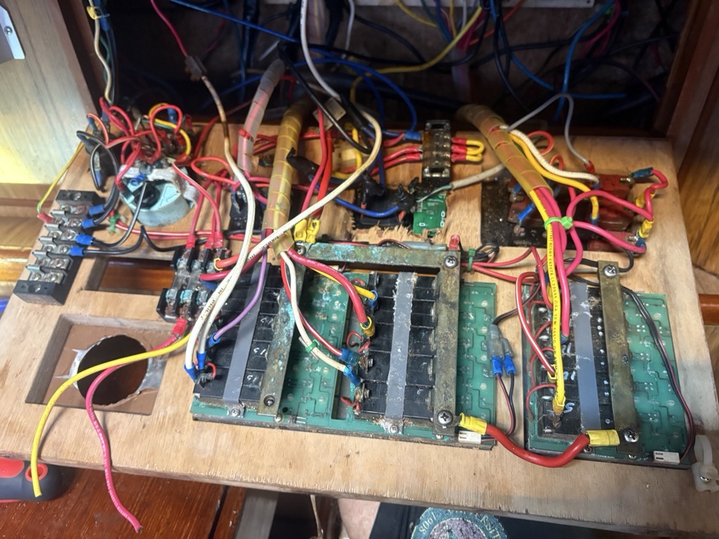
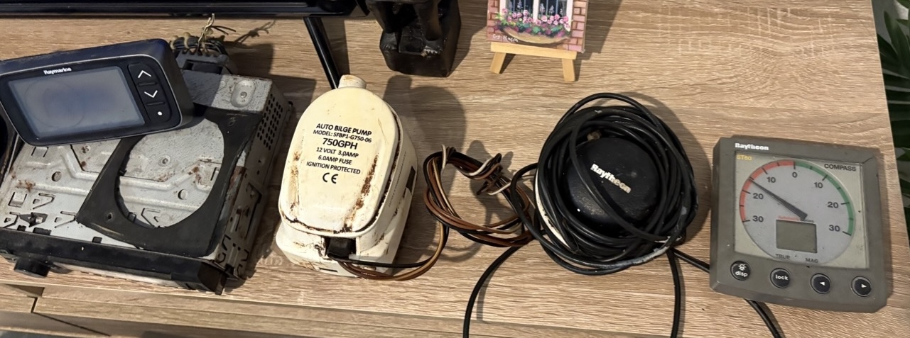
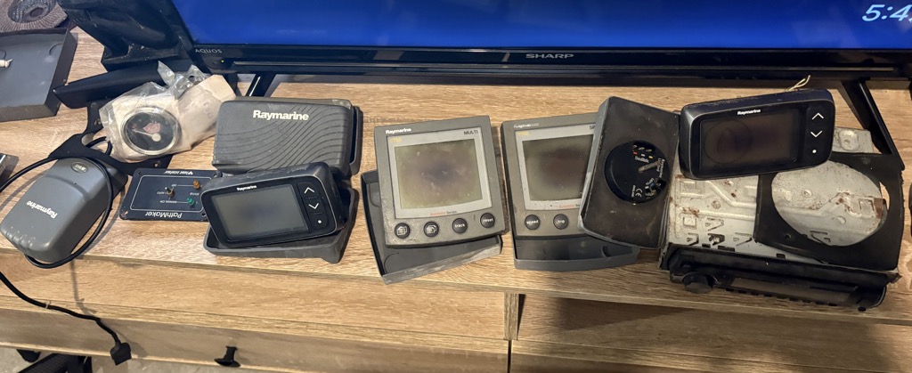
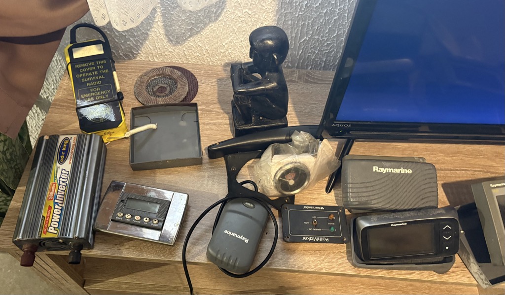
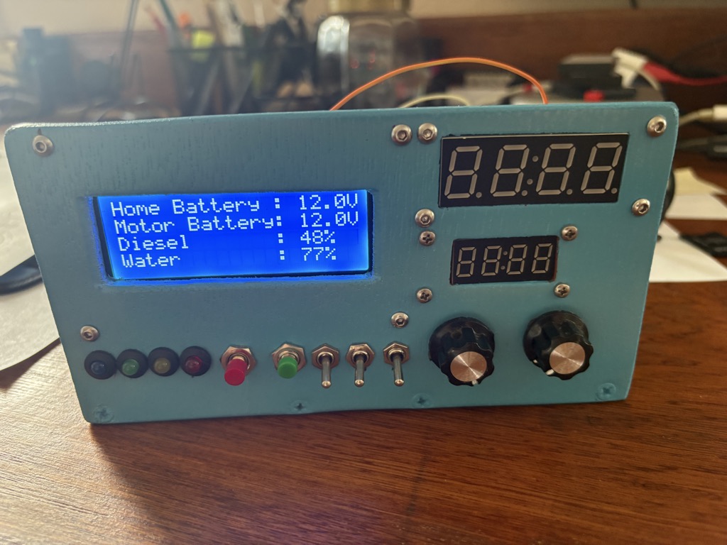
A lot of instrument junk and envisioning Hal 9002, the future artificial assistant of the boat
Well, this Looks bad. Even if the Instruments were not fried by the lightning, most of the displays have black spots. Most are Raymarine, with SeaTalk 2 bus, but some connectors are still SeaTalk 1.
Given the dire straits the instruments are it makes sense to completely design a new, economical system with OpenPlotter as central hub.
A new wheel autopilot costs between 1,600 and 2,500 US$. With OpenPlotter all is needed is a new wheel drive for around US$ 600 and a motor controller for 60 US$. Plus the Raspberry Pie and some additional components. And then you can connect all other devices to it too, creating a smart information center, just like the expensive stuff of the established companies. Let’s go for it and call it Hal 9002 as a working title.
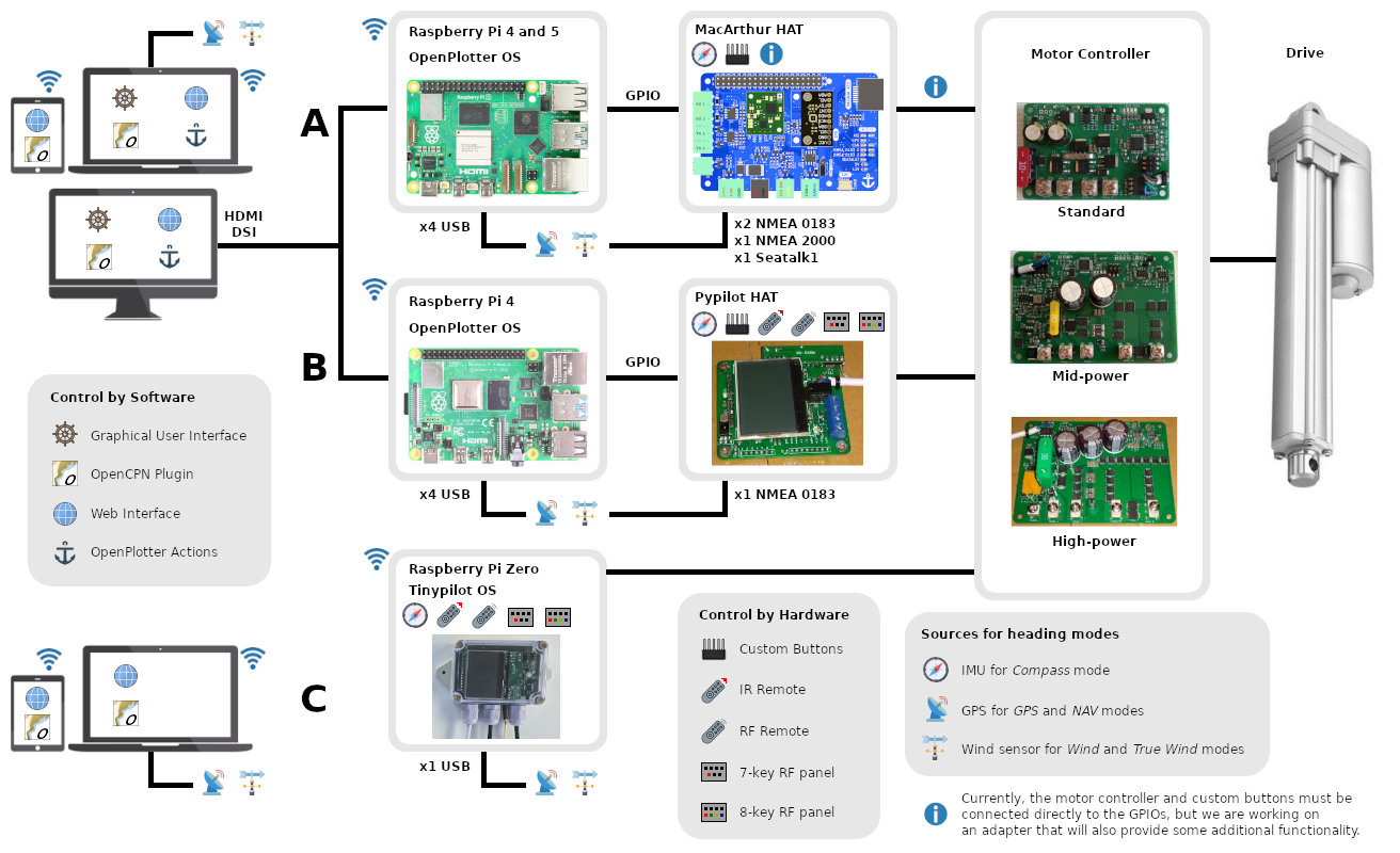
There are different ways to implement an OpenPlotter based system. I am going for option 2 with MacArthur Hat, since that requires least hardware interfacing.
Progress you can follow here:
The Hal 9002 page
Design of the new electrics
This is going to be my fourth new design of electrics for a sailing yacht after those of Magayon, Sancara, and Magayon II. Easy. I spend around 1.5 days to design the electric circuit diagram and layout the new control panel. After checking the existing system and controls that still work today, I will have to modify it a bit.
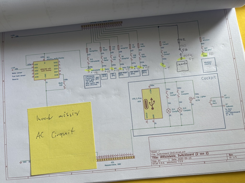
October 28: The second iteration of the electrical system design needs to fine tune the first draft. Some things to add:
- The fuel pump in the engine room.
- When getting up the mast to check on some blocks, the guy took some pictures of the mast top. There is no anchor light on top, only the three color light. Or only the anchor light. This will need an additional cable and a new top light.
- The water tanks don’t have level sensors. These need to be added.
Re-building the control panels / switch boards
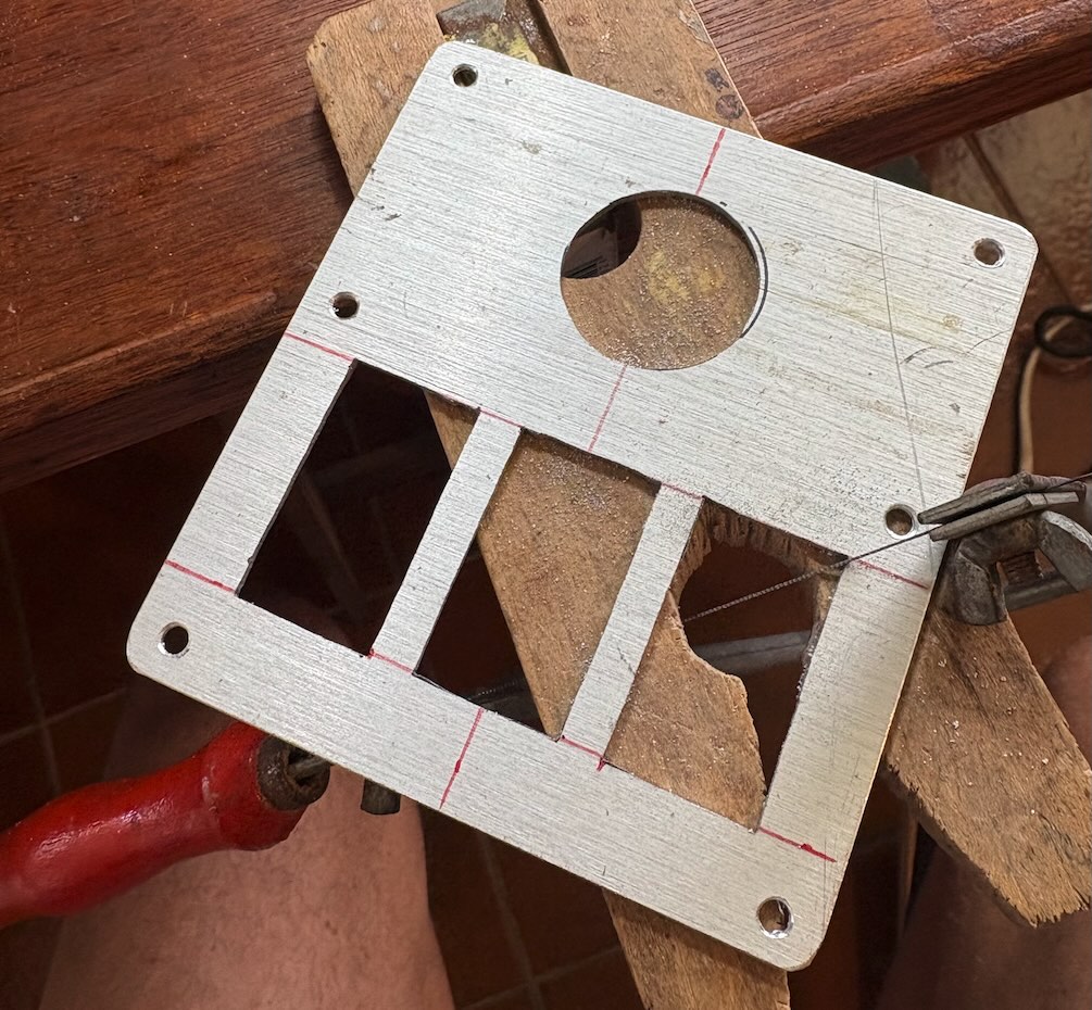
October 11: Switchboard panels from re-cycled flexible solar panel
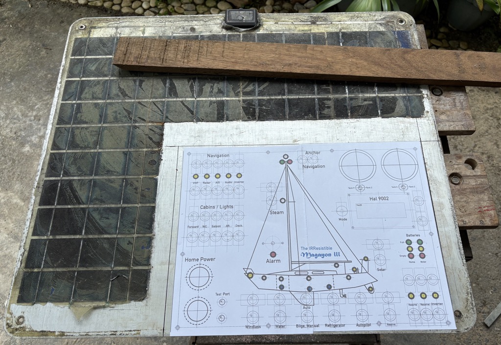
After 10 years use one of the bendable solar panels on Magayon II had started delaminating and lost power. It was supposed German quality, the cells laminated onto 1.5 mm thick seawater proof aluminum. Ideal material for the control panels. Remember, circular economy?
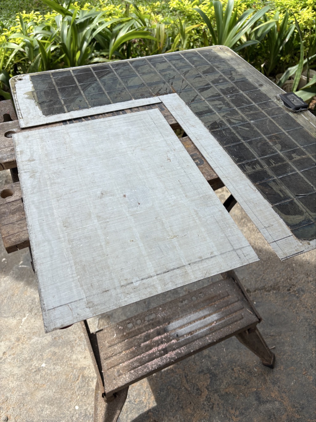
The first challenge was to remove the laminates containing the solar cells. It worked quite well with an electric heat gun, at around 100 °C the laminate became soft and could be removed of with a scraper. The remaining thin layer of lamination material could then be easily removed after soaking it in epoxy thinner for around 5 minutes. Wearing a gas mask with filter for organic gasses while doing this work is a good idea.
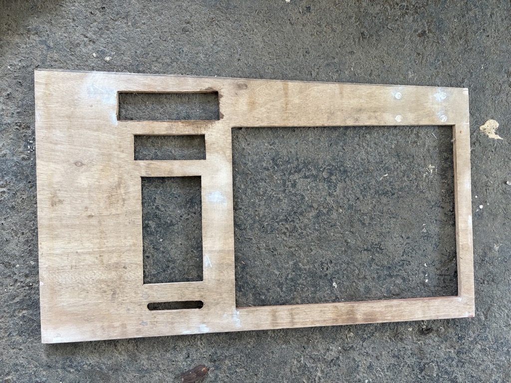
Left: Solar panel with solar cells partly removed. It is advisable to cut the edges of the aluminum sheet because there is usually a bit of corrosion on those.
A BOSCH jig saw with a blade for aluminum did a nice job. I used guide bars (see below) for a straight cut.
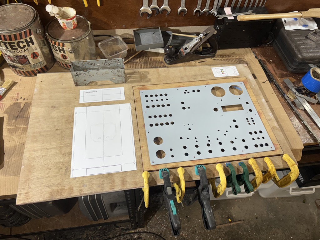
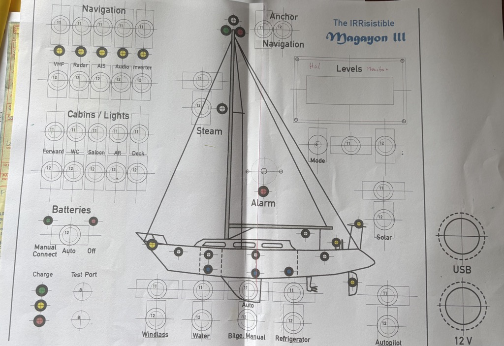
I designed the panels with Affinity Designer, printed them at 100% scale and used the printouts to arrange the different panels on the control board. The main switchboard panel is primed with gray etch primer and waiting for the flat black paint to arrive.
A bit of the challenge are the labels and the schematic diagram of the boat. The latter one I might airbrush. For the labels I am checking several print shops that can do vinyl. In the past I used LETRASET rub-on transfer letters for labels but in the internet time they are not available anymore.
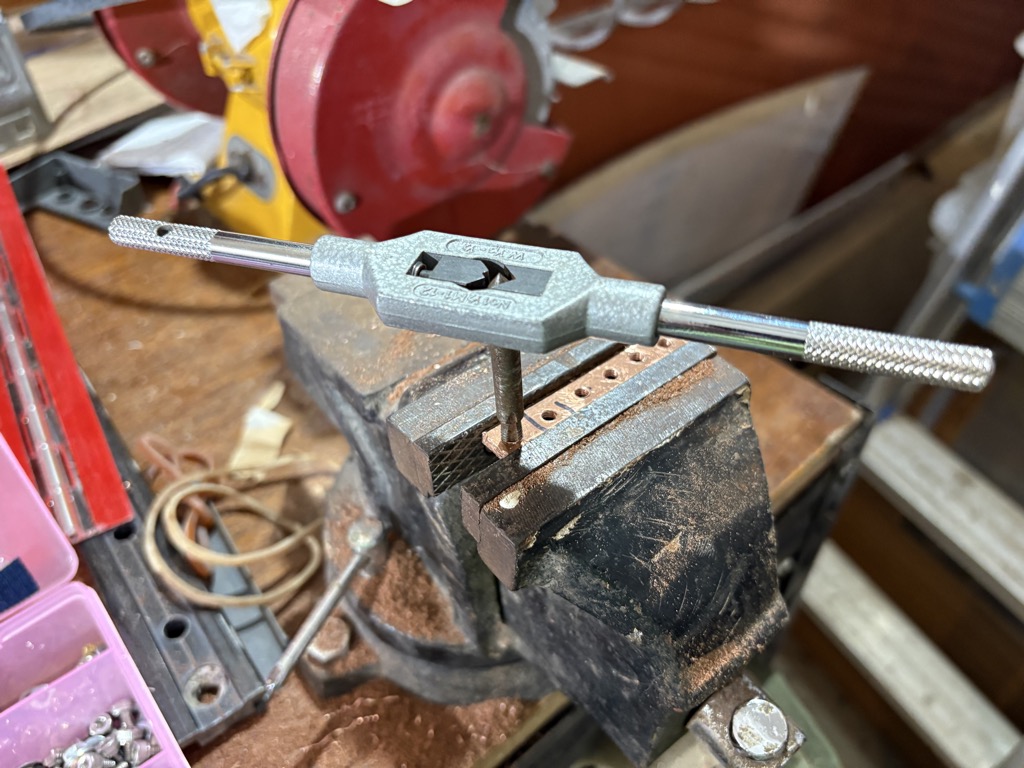
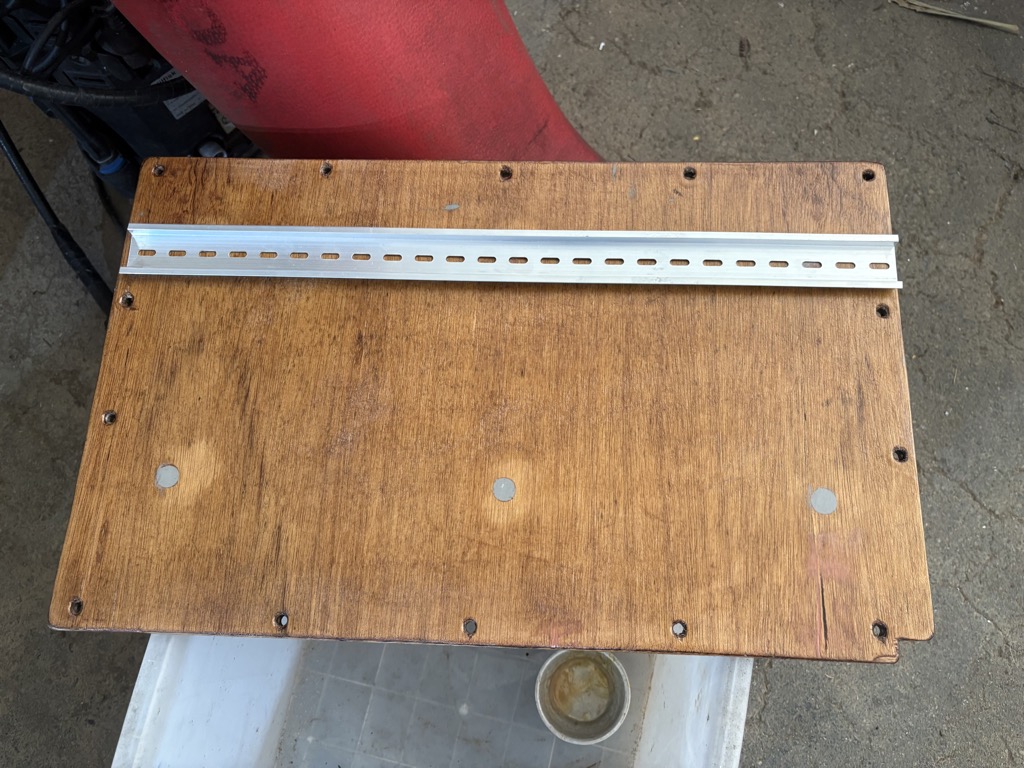
Using guide bars clamped on with vices for a straight cut with the jigsaw. The wood is Santa Clara marine plywood, a bit strained from previous work on Magayon II, but it will be painted anyway, so the spots don’t bother. All wood will be dried in the sun for a few days and then sealed with epoxy. All screws will have epoxy fillets to avoid water entering the wood through screw holes.
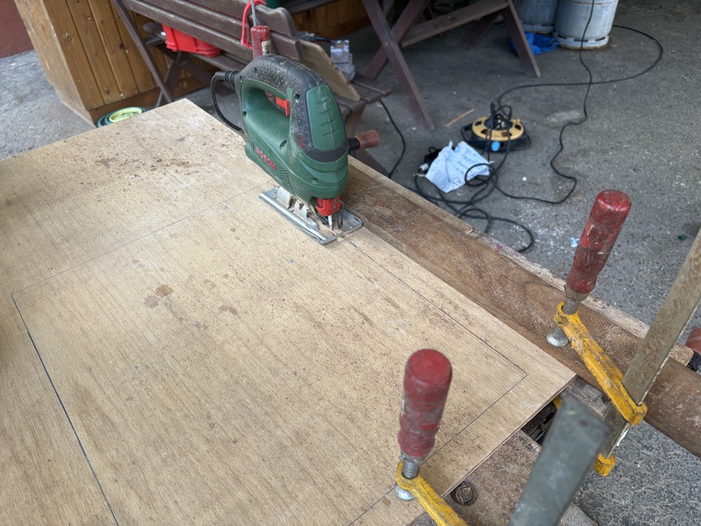
I will paint the panels white to give the interior a more roomy impression. So no need to be super careful with the wood surface. As long as the cut lines are straight.
October 26: Making progress with the switchboard.
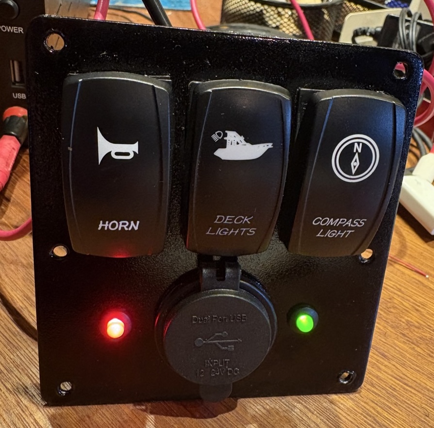
Took some time and several tests to figure out how to do the graphics and labels for the switchboards at affordable cost. In the past there were LETRASET Abreibebuchstaben (rub-on letters) in black or white, in different fonts. We used them at Bosch for individually manufactured panels. If you got it right (meaning straight with equal letter spacings) those looked very professional, and covered with clear lacquer lasted forever. No more. They are another victim of digitalization. There is only once company that still offers them. Decadry, for 34 Euro per sheet, but I did not find any white fonts and since I need different font sizes the price would be exorbitant.
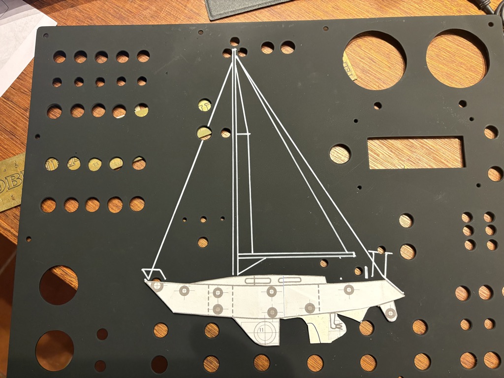
I also found single sheets with some letters already used on ebay for US$ 60 plus, traded as collectors items. And silly looking fonts only. So what I ended up with for the panels made from repurposed flexible solar panels: 1.) sanding the aluminium panel, 2.) applying 2 layers of etch primer, 3.) two layers of dull black acrylic epoxy as the base for the graphics, 4.) boat schematics done with white acrylic pen, 5.) Labels printed on self adhesive outdoor vinyl sticker film by ENTRELABEL and glued in place. 6.) a final layer of gloss clear lacquer to protect the graphics, seal the labels and for a semi gloss finish. The result looks good enough, a lot better than the pre manufactured switch panels with self adhesive labels.

around 50% of the materials needed I had on stock, accumulated over many years of doing electronics projects, 45% I bought online, and the remaining ones I made myself, like the GND bar from a small copper bar that I had in my stock too.
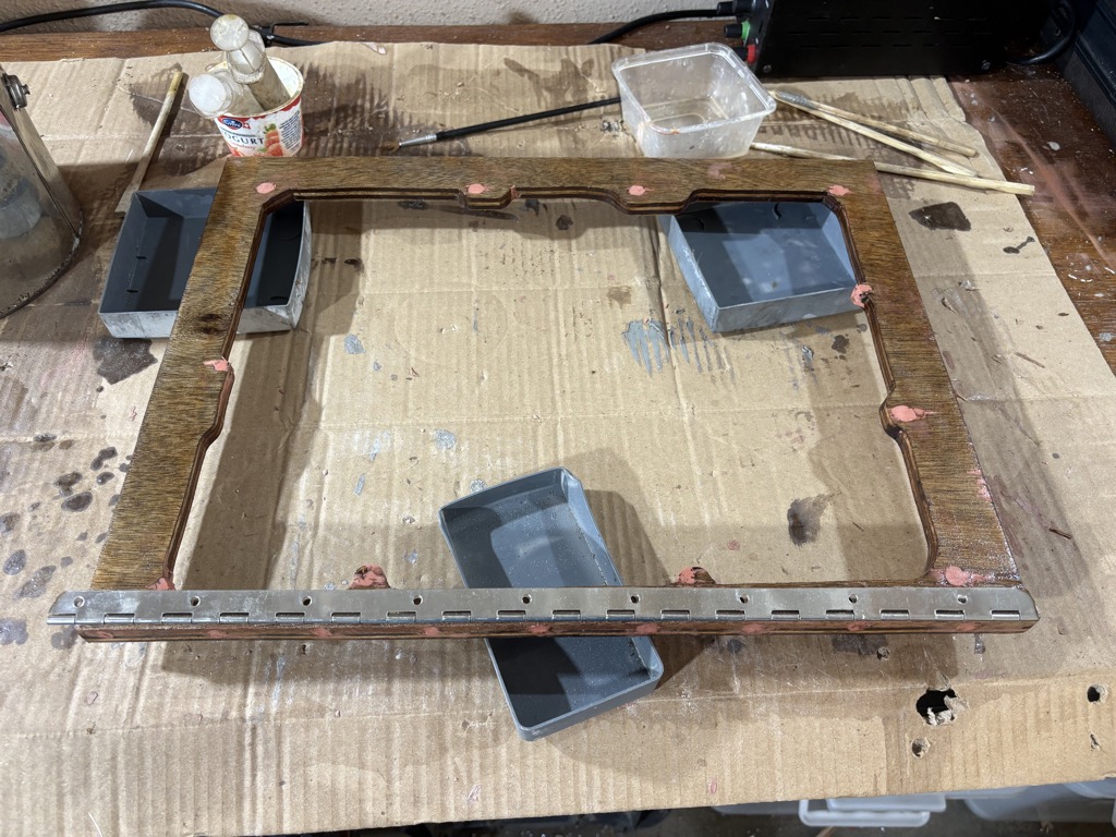
Base board for the terminal rails
The new base board will be a bit bigger and I will use DIN rails for the connections.

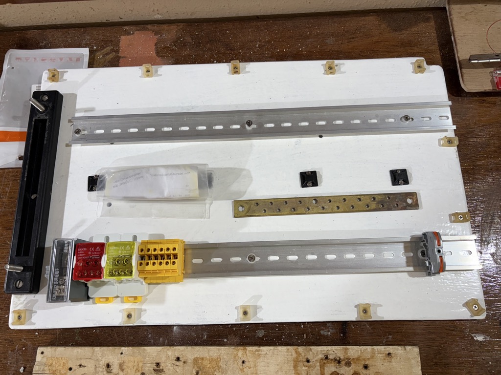
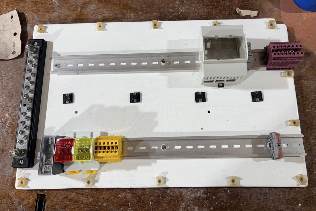
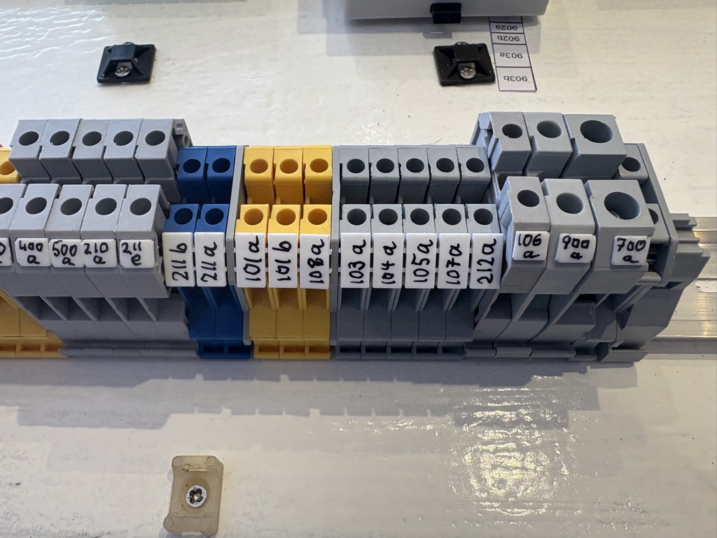
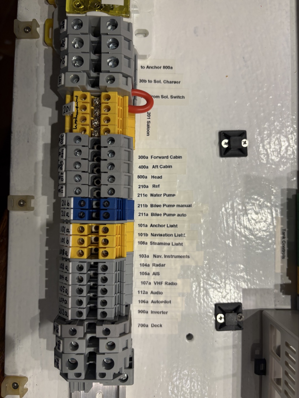
November 23: Good progress today and yesterday. I got all parts needed, except for one bridge or connecting terminals, but that is on the way.
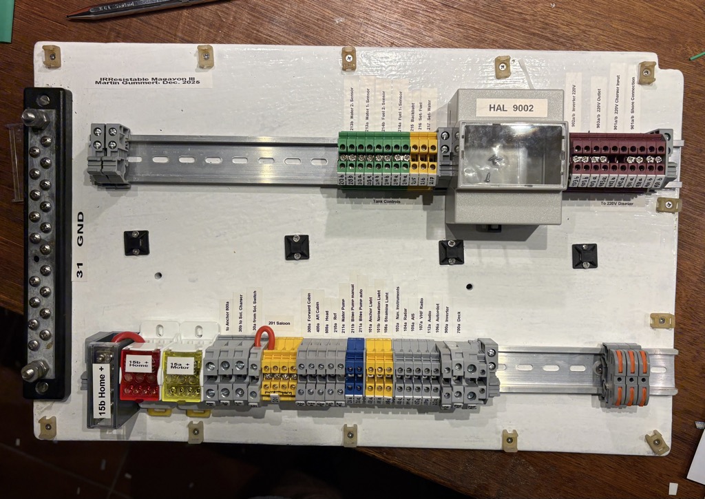
Got the DYMO LetraTag working and spent some significant time labelling all the terminal contacts. This time will easily be saved on the boat through more efficient work and less errors / error checking.
This is how far I can take it at home, now I need to continue on the boat, but another low pressure system is developing, maybe another Typhoon.
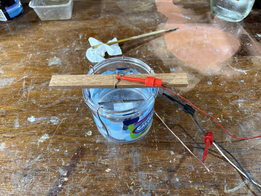
For the new wiring I am using highly flexible tinned copper wires. With ferrules at the ends for long life. Why ferrules? The old electric system did not have any?
Without a ferrule, the strands of a wire can easily spread out and get damaged, or break off, leading to a poor connection and potential electrical failure. Ferrules also reduce contact resistance between the wire and the connector. They also minimize oxidation in the strands due to the lack of air space between them. In connectors with screws they protect the strands from getting turned and ripped of by the turning screw.
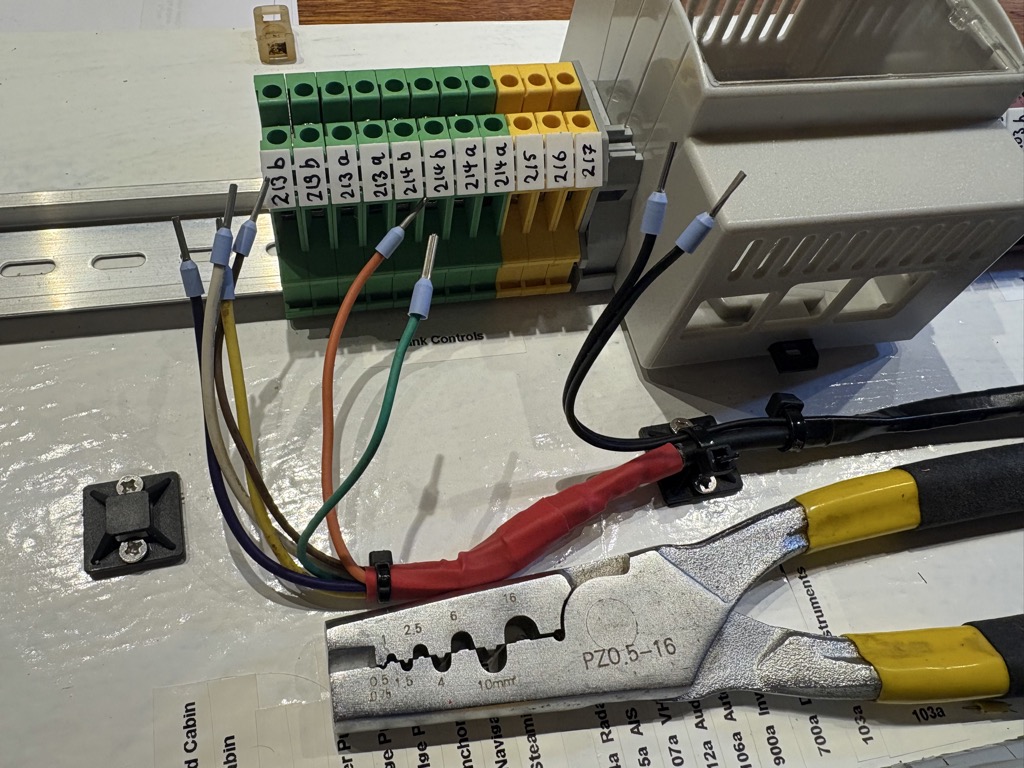
They basically protect the wire and ensure a long lasting connection.
One should always use them. It is basically Best Practice.

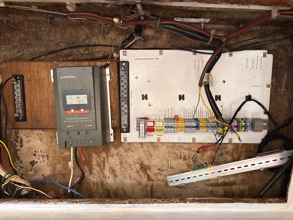
November 29: A major step. The solar charger location is still temporary. Once I have sorted out the battery compartment and the large power wires the fun starts: Connecting all the devices and making them work.
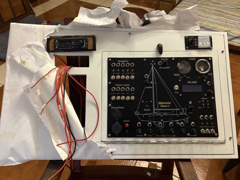
The 220V AC Panel
Our parents gave us a head start in tinkering. As children we got a lot of Graupner “Laubsäge Arbeits Brettchen”. After doing around 10 of them with a jigsaw, my cuts were perfect, and they still are 🙂
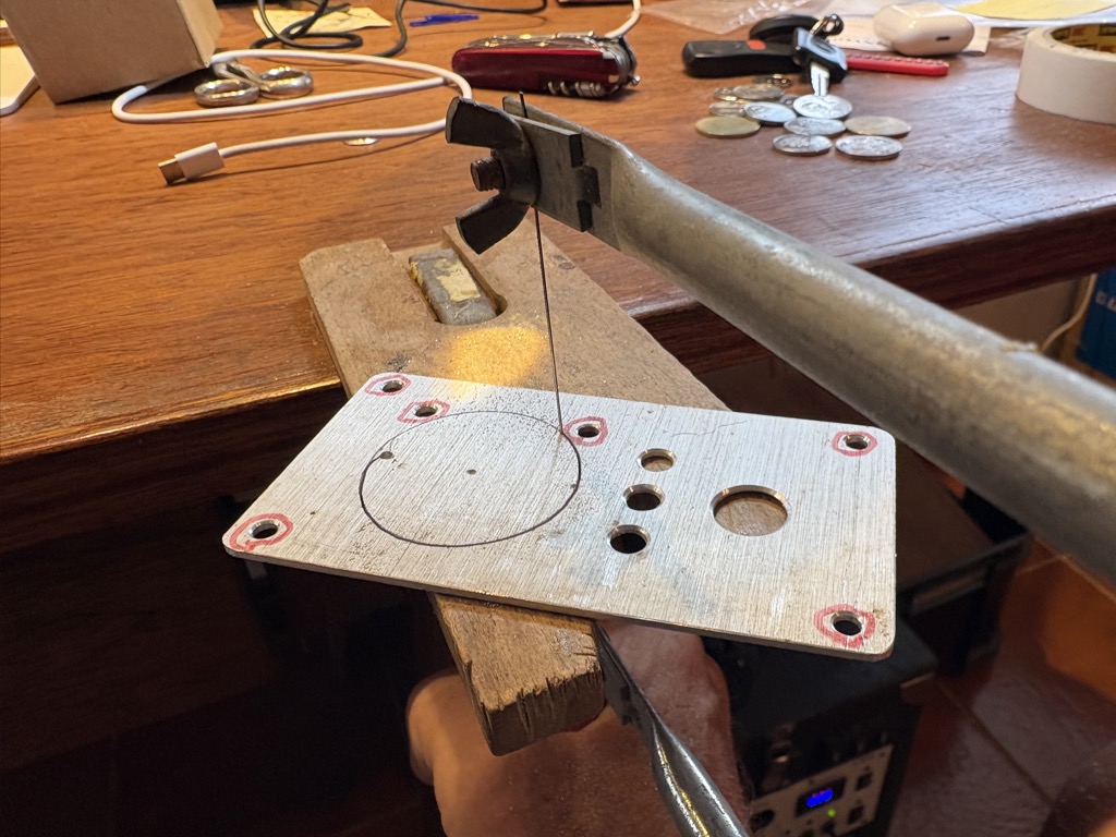
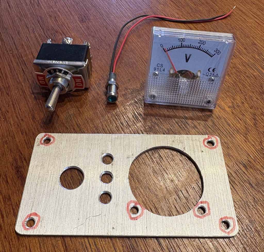
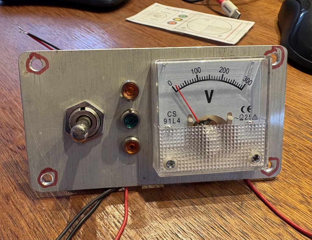
October 13: Another good use of the former solar panel. The 220V AC Panel is separate from the main switchboard panel. So that it can be easily replaced should I opt for a more advanced 220V system later. For now it will just show the voltage and allow to chose either shore power or the inverter as the power source. I like old school analog instruments. For this purpose the accuracy is good enough.

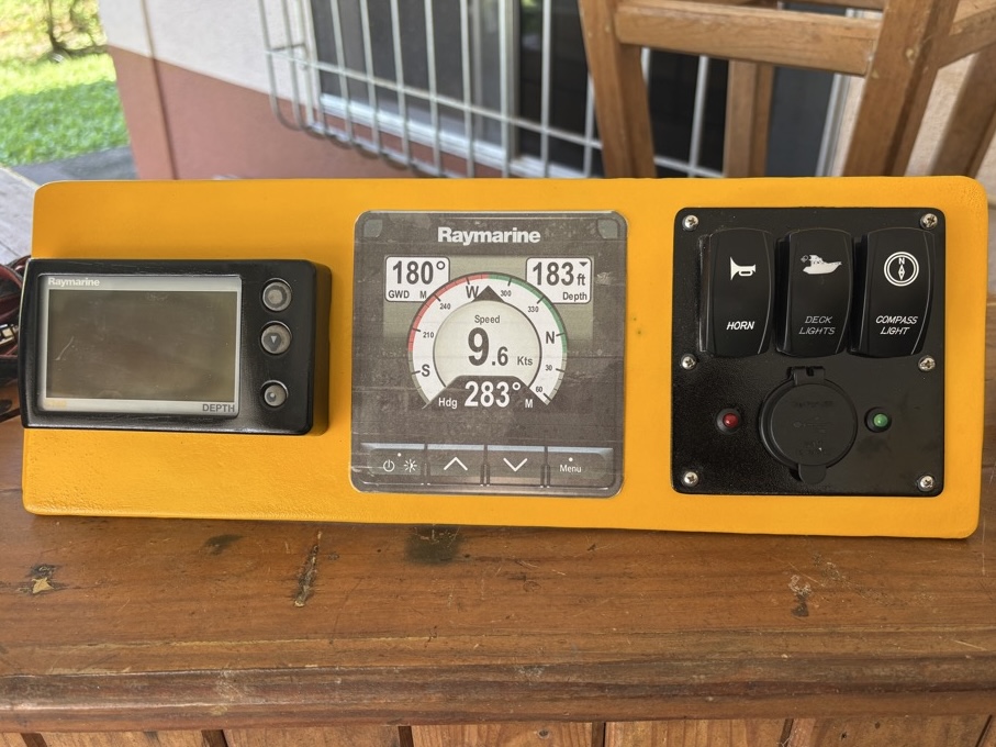
Cockpit Panels
Music
Yes, of course we need music. And I love good quality sound. The radio that came with a boat was a PIONEER with lots of bells and whistles. Karaoke, random playlist generation etc etc. I hate that crap. I want to have full control and as little as possible useless functions and flashing lights. What made it worse, when I connected it to speakers and an input source there was no sound. So probably fried too. So we need a new one. But given that this is a restoration on a budget, I’ll postpone the purchase of a radio to later, but will add a DIN1 slot in the control panel. In the meantime I’ll fit a boombox bluetooth controller that I still have from a previous project. It has a 2x25W amplifier, a FM radio and a remote control, so that music can be played during the restoration and until we find a better radio. The quality is not too good, base missing totally. But hey, baseless music is better than no music.
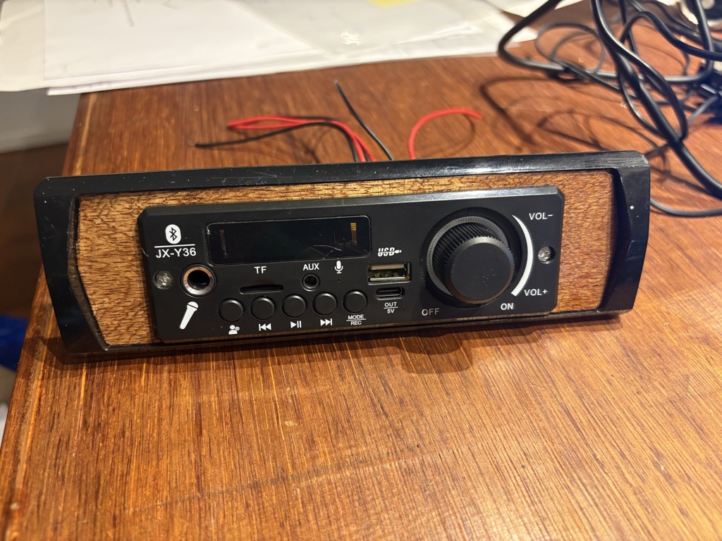
Total cost: US$ 10.
Sorting out the Starboard Battery Compartment
It is too much work to replace the bulkhead, which is rotten at the areas where water was running down from the traveler leaks. Maybe after the haul out if the Hull turns out to be OK that could be an option.
October 15: First steps, sorting out the cable mess and cleaning the starboard battery compartment.
October 29: Since I want to transfer the cable connections from the battery poles to proper terminals, I need a sound wooden base for holding the terminals. I therefore strengthened the bulkhead with plywood sheets.
November 29: Three days to work on electrical stuff. The first step is to sort out the battery compartment. The strap that was used to hold the battery in place was broken. The battery was moving freely, with every tack it slid to the leeward side. Since the boat heels a lot, there must have been quite some forces at play. The battery was sitting also loosely on a jungle of cables. Which might have made things worse, or buffered the movements, who knows. All plus cables were directly connected to the battery pole, presenting the observer with a total mess, what the heck is what?
True fiberglass hull looks very messy, at some point it should be cleaned and get a new coat. But not now. There are so many high priority items to fix first.
Terminals and Connectors
All large power cables connecting the batteries were replaced in 2008, when the boat got a major overhaul. However, due to the moist environment inside all connectors and most copper wires are heavily corroded. They all need to be replaced.